

[vc_row][vc_column][vc_column_text]
Why Fly Long Range FPV?
With the recent release of new and more affordable radio link and FPV technology, long range FPV has been gaining traction within the FPV community more rapidly than ever before. More and more pilots are pushing their gear (and nerve!) to the outer limits in order to experience FPV in its most purest unrestricted form. No longer is the park border the final boundary, long range pilots are free to reach for the next mountain, furthest peak, or even the next township over. There’s never been a better time than now to fly long range FPV![vc_column][vc_column_text]
“Imagine if a Lamborghini and a stealth attack helicopter had a baby”
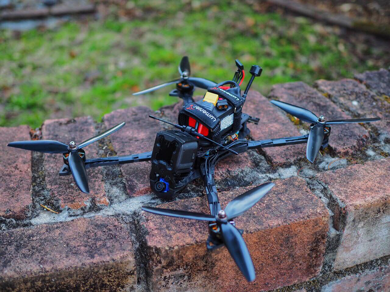
The featured frame in this build guide is the Falcon Multirotors Raggio Lungo, available directly from GetFPV here. Unsure if the Raggio Lungo is the right frame for you? Take a look at GetFPV’s ‘Beginners Guide to Long Range FPV’.
The Raggio Lungo is a TPU accesorized carbon fiber frame, naturally kitted out in full stealth black. Measuring 300mm motor to motor, the Raggio effortlessly swings both 6″ and 7″ props. Despite its rugged carbon fiber construction and roomy internals, the Raggio weighs in at just 150g, a miracle considering the sheer size of this beefy frame. Construction is straightforward and maintenance is an absolute breeze with the included inset nuts and ‘pop-top’ plate.
The selected power train is no less impressive: TMotor F40 Pro II motors swinging hyper-responsive HQ 7″ props on 6S grants the Raggio ridiculously high cruising speed and plenty of pep. The XRotor 45A 4-in-1 ensures the motors can draw the amps they deserve, while the G2 FC keeps the Raggio locked in and cruising like it’s on rails.[/vc_column_text][/vc_column][/vc_row][vc_row][vc_column][vc_column_text]
You can also purchase this build bundle from GetFPV here.
The Components
All parts used in this long range build were selectively hand-picked from GetFPV’s broad selection of high quality FPV components. Be certain these trustworthy components will not fail you while you’re going the distance.[/vc_column_text][ultimate_spacer height=”32″][dt_default_button link=”url:https%3A%2F%2Fwww.getfpv.com%2Flong-range-fpv-quadcopter-raggio-lungo-arf.html||target:%20_blank|” size=”big” btn_width=”btn_full_width” default_btn_bg_color=”#ffcd32″ bg_hover_color=”#ffc10a”]BUY ENTIRE LONG RANGE FPV BUNDLE NOW[/dt_default_button][/vc_column][/vc_row][vc_row][vc_column width=”1/2″][vc_single_image image=”3130″ alignment=”center”][/vc_column][vc_column width=”1/2″][vc_column_text]
Frame – Falcon Multirotors Raggio Lungo
A rugged and versatile long range FPV frame.
Available from GetFPV for $99.99[/vc_column_text][/vc_column][/vc_row][vc_row][vc_column width=”1/2″][vc_single_image image=”3135″ alignment=”center”][/vc_column][vc_column width=”1/2″][vc_column_text]
Motors – TMotor F40 Pro II 1600kV
Tiger Motor’s latest offering in the F40 Pro line, the perfect balance of intense power and smoothness for long range operations.
Available from GetFPV for $26.90[/vc_column_text][/vc_column][/vc_row][vc_row][vc_column width=”1/2″][vc_single_image image=”3136″ alignment=”center”][/vc_column][vc_column width=”1/2″][vc_column_text]
FC/ESC Combo – Hobbywing XRotor Micro V2 Combo: F4 G2 FC and 45A BlHeli_32 4-in-1
The long-awaited update to the much loved XRotor Micro V1 FC/ESC combo provides peak performance in a seamless package.
Available from GetFPV for $99.99[/vc_column_text][/vc_column][/vc_row][vc_row][vc_column width=”1/2″][vc_single_image image=”3137″ alignment=”center”][/vc_column][vc_column width=”1/2″][vc_column_text]
Receiver – TBS Crossfire Nano Special Edition
Team Blacksheep’s crossfire system has been the gold standard of long range reliability since its conception, and the TBS Crossfire Nano equipped with SE ‘Immortal T’ is no exception.
Available from GetFPV for $44.99[/vc_column_text][/vc_column][/vc_row][vc_row][vc_column width=”1/2″][vc_single_image image=”3140″ alignment=”center”][/vc_column][vc_column width=”1/2″][vc_column_text]
FPV Camera – Foxeer Predator Micro V3
Foxeer’s popular micro FPV camera, boasting a crisp and vibrant image.
Available from GetFPV for $36.99[/vc_column_text][/vc_column][/vc_row][vc_row][vc_column width=”1/2″][vc_single_image image=”3141″ alignment=”center”][/vc_column][vc_column width=”1/2″][vc_column_text]
Video Transmitter – TBS Unify Pro HV SMA
The TBS Unify Pro HV VTX has been the 5.8gHz long range standard since its release. Capable of outputting up to 800mW in a marvellously compact package, the Unify Pro fits comfortably into any long range build.
Available from GetFPV for $49.99[/vc_column_text][/vc_column][/vc_row][vc_row][vc_column width=”1/2″][vc_single_image image=”3151″ alignment=”center”][/vc_column][vc_column width=”1/2″][vc_column_text]
Antenna – Lumenier AXII
Among the smallest and most compact 5.8gHz antennas available for FPV today, the AXII may be tiny although it does not compromise on range and signal quality.
Available from GetFPV for $39.99 (Set of two)
[/vc_column_text][/vc_column][/vc_row][vc_row][vc_column width=”1/2″][vc_single_image image=”3138″ alignment=”center”][/vc_column][vc_column width=”1/2″][vc_column_text]
GPS – Holybro Micro M8N UBLOX GPS
The industry standard M8N GPS, boasting faster satellite connection speeds than M7N GPS modules.
Available from GetFPV for $36.99[/vc_column_text][/vc_column][/vc_row][vc_row][vc_column][vc_column_text]
Optional Components
[/vc_column_text][/vc_column][/vc_row][vc_row][vc_column width=”1/2″][vc_single_image image=”3154″ alignment=”center”][/vc_column][vc_column width=”1/2″][vc_column_text]
Lumenier Digital RGB LED Arm Board
Affordable compact RGB LEDs.
Available from GetFPV for $2.99/pc[/vc_column_text][/vc_column][/vc_row][vc_row][vc_column width=”1/2″][vc_single_image image=”3152″ alignment=”center”][/vc_column][vc_column width=”1/2″][vc_column_text]
Lumenier LED PDB
A convenient power distribution board for Lumenier RGB LEDs.
Available from GetFPV for $3.74[/vc_column_text][/vc_column][/vc_row][vc_row][vc_column width=”1/2″][vc_single_image image=”3153″ alignment=”center”][/vc_column][vc_column width=”1/2″][vc_column_text]
Lumenier Multi-Functional RGB LED Tail Light
A highly customisable RGB LED tail light with many configurations and functions.
Available from GetFPV for $16.99[/vc_column_text][/vc_column][/vc_row][vc_row][vc_column][ultimate_spacer height=”32″][dt_default_button link=”url:https%3A%2F%2Fwww.getfpv.com%2Flong-range-fpv-quadcopter-raggio-lungo-arf.html||target:%20_blank|” size=”big” btn_width=”btn_full_width” default_btn_bg_color=”#ffcd32″ bg_hover_color=”#ffc10a”]BUY ENTIRE LONG RANGE FPV BUNDLE NOW[/dt_default_button][ultimate_spacer height=”32″][vc_column_text]
The Build Process
As far as FPV drone builds go, the Raggio Lungo isn’t particularly demanding, being relatively spacious and simple to assemble. This build guide will focus on wiring, binding, software setup and calibration rather than build techniques. For a detailed article on various FPV drone building techniques, read Drone Build Tips and Tricks Part One.[/vc_column_text][vc_single_image image=”3256″ img_size=”large” alignment=”center” onclick=”link_image”][/vc_column][/vc_row][vc_row][vc_column width=”1/2″][vc_column_text]
Tools required:
- A soldering iron
- One fine and one broad soldering iron tip
- Wire cutters
- Pliers
- Shifter wrench / Prop tool
- Penknife
- Heatgun/lighter
- 2mm hex-head driver
- 1.5mm hex-head driver
[/vc_column_text][/vc_column][vc_column width=”1/2″][vc_column_text]
Build materials:
- Heat shrink, varying diameter (1mm – 30mm)
- Electric tape
- Thin foam sheet
- Hot glue
- Double-sided tape
- Zip-ties
- Nylon spacers, bolts and nuts
[/vc_column_text][/vc_column][/vc_row][vc_row][vc_column][vc_column_text]
Step One: Frame Assembly
- Parts: Raggio Lungo carbon fiber frame and hardware
- Tools: 2mm hex driver (not pictured)
[/vc_column_text][vc_separator el_width=”50″][vc_column_text]
- Insert 8x 10mm countersunk M3 screws through the arm holes of the base plate. Place an arm in each arm slot.
[/vc_column_text][vc_column_text]
- Place an arm brace on each pair of arms, protruding inset nuts facing upward. Carefully thread each of the eight bolts into the inset nuts, being careful not to over-torque the bolts and strip the heads.
[/vc_column_text][vc_column_text]
- Next, thread 3x M3x14 buttonhead screws into the base of the supplied 3D printed camera turret. Slot the turret into the underside of the front of the frame.
[/vc_column_text][vc_column_text]
- Push the provided 3D printed GoPro mount on to the camera turret bolts. Slide the fastening plate through the gap in the GoPro mount with the inset nuts facing upwards. Tighten the bolts to fasten the GoPro mount and camera turret to the frame.
[/vc_column_text][vc_column_text]
- Fasten 4x 20mm standoffs to the base plate using 4x M3x6 countersunk bolts. Place the top plate over the standoffs and firmly attach it with another 4x M3x6 countersunk bolts.
[/vc_column_text][vc_column_text]
- With frame assembly out of the way, it’s time to move on to the power train.
[/vc_column_text][ultimate_carousel slides_on_desk=”2″ slides_on_tabs=”2″ slides_on_mob=”1″ item_animation=”fadeIn” adaptive_height=”on” item_space=”5″][vc_single_image image=”3234″ img_size=”full” alignment=”center” onclick=”link_image”][vc_single_image image=”3246″ img_size=”full” alignment=”center” onclick=”link_image”][vc_single_image image=”3248″ img_size=”full” alignment=”center” onclick=”link_image”][vc_single_image image=”3249″ img_size=”full” alignment=”center” onclick=”link_image”][vc_single_image image=”3250″ img_size=”full” alignment=”center” onclick=”link_image”][vc_single_image image=”3251″ img_size=”full” alignment=”center” onclick=”link_image”][vc_single_image image=”3252″ img_size=”full” alignment=”center” onclick=”link_image”][vc_single_image image=”3253″ img_size=”full” alignment=”center” onclick=”link_image”][vc_single_image image=”3254″ img_size=”full” alignment=”center” onclick=”link_image”][vc_single_image image=”3255″ img_size=”full” alignment=”center” onclick=”link_image”][/ultimate_carousel][/vc_column][/vc_row][vc_row][vc_column][vc_column_text]
Step One.Five: Pinout Diagram to Reference
- Use this pinout diagram as a visual reference to make sure that your quad is wired up correctly for Steps 2-6.
[/vc_column_text][vc_row_inner][vc_column_inner width=”1/6″][/vc_column_inner][vc_column_inner width=”2/3″][vc_single_image image=”3346″ img_size=”full” alignment=”center” onclick=”link_image”][/vc_column_inner][vc_column_inner width=”1/6″][/vc_column_inner][/vc_row_inner][/vc_column][/vc_row][vc_row][vc_column][vc_column_text]
Step Two: Power Train
- Parts: 4x F40 Pro II, XRotor 45A 4-in-1, 2x 3D printed Nylon feet
- Materials: 4x 3mm spacer (standard nylon nuts are perfect), 4x M3x20 nylon bolt, 8x M3X6 button-head steel bolt, 6x M3x10 button-head steel bolt
- Tools: 2mm hex driver, phillips head driver, wire cutters, penknife, soldering iron
[/vc_column_text][vc_separator el_width=”50″][vc_column_text]
- Bolt a pair of motors to the two front arms with 8x M3x6 button-head screws. Slot a landing foot on to the underside of each rear motor mount. Pass an M3x10 button-head screw through each opening and bind a motor to each rearward mount.
[/vc_column_text][vc_column_text]
- Insert an M3x20 nylon screw through the mounting holes of the base plate. Place a 3mm spacer over each screw and seat the XRotor 4-in-1 firmly on the stack mount. Before soldering the motor wires to the 4-in-1, generously pre-tin the pads.
[/vc_column_text][vc_column_text]
- Measure each motor wire so that it comfortably reaches its designated pad on the 4-in1. Sever the excess wire with the wire cutters and strip the insulation with a penknife or a pair of wire strippers. Be sure to tin each wire before soldering it on to the 4-in-1. Note: When the 4-in-1 is positioned in this way, the motor numbers will not match up correctly. This can and will be fixed later on.
[/vc_column_text][vc_column_text]
- Next, cut the provided XT60 pigtail to 70mm in length and solder it on to the 4-in-1, being sure to tin the wires with ample solder.
[/vc_column_text][vc_column_text]
- Before plugging the provided JST connector into the 4-in-1, use a penknife to release the signal wires from the JST connector. Exchange signal wire one with four, and signal wire two with three. If this is not done, the motors will spin incorrectly.
[/vc_column_text][ultimate_carousel slides_on_desk=”2″ slides_on_tabs=”2″ slides_on_mob=”1″ item_animation=”fadeIn” adaptive_height=”on” item_space=”5″][vc_single_image image=”3257″ img_size=”full” alignment=”center” onclick=”link_image”][vc_single_image image=”3259″ img_size=”full” alignment=”center” onclick=”link_image”][vc_single_image image=”3260″ img_size=”full” alignment=”center” onclick=”link_image”][vc_single_image image=”3261″ img_size=”full” alignment=”center” onclick=”link_image”][vc_single_image image=”3262″ img_size=”full” alignment=”center” onclick=”link_image”][/ultimate_carousel][/vc_column][/vc_row][vc_row][vc_column][vc_column_text]
Step Three: Flight Controller
- Parts: G2 FC
- Materials: 4x 3mm spacer
- Tools: Soldering iron, wire cutter, penknife
[/vc_column_text][vc_separator el_width=”50″][vc_column_text]
- Place a 3mm spacer over each mounting screw threaded through the 4-in-1 ESC. Check there is a sufficient gap between the FC and ESC or an electrical short can occur. Next, situate the G2 FC on top of the spacers, aligning the directional arrow with the front of the craft. Plug the JST connector running from the FC into the flight controller.
[/vc_column_text][vc_column_text]
- Prior to plugging in the silicone wired JST connector, remove the 10V, GND and UART6-Rx wires. Press the modified JST connector into the sideward port of the flight controller.
[/vc_column_text][vc_row_inner][vc_column_inner width=”1/6″][/vc_column_inner][vc_column_inner width=”2/3″][vc_single_image image=”3264″ img_size=”full” alignment=”center” onclick=”link_image”][/vc_column_inner][vc_column_inner width=”1/6″][/vc_column_inner][/vc_row_inner][/vc_column][/vc_row][vc_row][vc_column][vc_column_text]
Step Four: FPV System
- Parts: Foxeer Predator Micro, TBS Unify Pro HV, Lumenier AXII, Raggio Lungo 3D printed GPS/SMA mount
- Materials: Double-sided tape, 2x M2x6mm button-head screw, 1mm ID heat shrink
- Tools: Soldering iron, wire cutters, penknife, heatgun / lighter
[/vc_column_text][vc_separator el_width=”50″][vc_column_text]
- Tuck the predator micro camera into the camera turret, securing tightly with a couple of M2x6 screws. Plug the supplied wiring harness into the camera.Note: This is a good time to edit camera settings before continuing. For an excellent article on FPV camera settings, have a look at Josh Cook’s ‘Getting the Right FPV Drone Camera Settings’ article.
[/vc_column_text][vc_column_text]
- Slide the 3D printed antenna/GPS mount over the rear standoffs, push the Unify Pro SMA through the mount and secure it by tightening the AXII antenna. Stick the Unify Pro to the base plate using double-sided tape. Ensure that the coaxial cable is unstressed.
[/vc_column_text][vc_column_text]
- Remove the audio cable from the included Unify Pro wiring harness. Plug the harness into the JST connector.
[/vc_column_text][vc_column_text]
- Camera wiring:
– Camera ‘VID’ to FC ‘Video In’
– Camera ‘GND’ to VTX ‘GND Out’
– Camera ‘VCC’ to VTX ‘5V Out’ - VTX wiring:
– VTX ‘VID’ to FC ‘Video Out
– VTX ‘Smart Audio’ to FC ‘UART6-Tx’
– VTX ‘HV In’ to FC ’10V’
– VTX ‘GND In’ to FC ‘GND’
[/vc_column_text][ultimate_carousel slides_on_desk=”2″ slides_on_tabs=”2″ slides_on_mob=”1″ item_animation=”fadeIn” adaptive_height=”on” item_space=”5″][vc_single_image image=”3266″ img_size=”full” alignment=”center” onclick=”link_image”][vc_single_image image=”3267″ img_size=”full” alignment=”center” onclick=”link_image”][/ultimate_carousel][/vc_column][/vc_row][vc_row][vc_column][vc_column_text]
Step Five: Receiver
[/vc_column_text][vc_column_text]
- Parts: TBS Crossfire Nano RX, TBS Crossfire Immortal T
- Materials: Double-sided tape, included heat shrink
- Tools: Soldering iron, wire cutters, penknife, heatgun / lighter
- Resources: TBS Crossfire Nano RX Quickstart Guide
[/vc_column_text][vc_separator el_width=”50″][vc_column_text]
- Slot the Immortal T antenna into the antenna holder attached to the top of the GoPro. Gently clip the antenna UFL on to the Nano RX. Pre-tin four wires and solder each on to the primary Nano RX pads (GND, 5V IN, CH. OUT 1 and CH. OUT 2). Slide the included clear heat shrink over the RX and heat it, allowing it to set before handling again.
[/vc_column_text][vc_column_text]
- Now, wire the Nano RX to the FC.
– RX ‘GND’ to FC ‘GND’
– RX ‘5V IN’ to FC ‘5V’
– RX ‘CH. OUT 1’ to FC ‘UART1-Rx’
– RX ‘CH. OUT 2’ to FC ‘UART1-Tx’
[/vc_column_text][ultimate_carousel slides_on_desk=”2″ slides_on_tabs=”2″ slides_on_mob=”1″ item_animation=”fadeIn” adaptive_height=”on” item_space=”5″][vc_single_image image=”3269″ img_size=”full” alignment=”center” onclick=”link_image”][vc_single_image image=”3271″ img_size=”full” alignment=”center” onclick=”link_image”][/ultimate_carousel][/vc_column][/vc_row][vc_row][vc_column][vc_column_text]
Step 6: GPS
[/vc_column_text][vc_column_text]
- Parts: Holybro Micro M8N GPS, 3D Printed Raggio Lungo GPS Mount
- Materials: 4x M3x6 nylon bolt, 4x M3 nylon nut
- Tools: Soldering iron, wire cutters, penknife, phillips head driver
- Resources: Holybro Micro M8N GPS Manual
[/vc_column_text][vc_separator el_width=”50″][vc_column_text]
- Firstly, decase the GPS module by unscrewing the four retaining screws with a phillips head driver. Slide the decased GPS module into the 3D printed mount, fastening it there with the nylon bolts and nuts.
[/vc_column_text][vc_column_text]
- Remove the ‘SDA’ and ‘SCL’ pins from the GPS JST connector and trim to length, exposing the bare wires. Tin each wire tip before soldering it to the FC.
[/vc_column_text][vc_column_text]
- Solder the GPS wiring harness to the FC.
– GPS ‘GND’ to FC ‘GND’
– GPS ‘5V’ to FC ‘5V’
– GPS ‘TXD’ to FC ‘UART3-Rx’
– GPD ‘RXD’ to FC ‘UART3-Tx’
[/vc_column_text][ultimate_carousel slides_on_desk=”2″ slides_on_tabs=”2″ slides_on_mob=”1″ item_animation=”fadeIn” adaptive_height=”on” item_space=”5″][vc_single_image image=”3272″ img_size=”full” alignment=”center” onclick=”link_image”][vc_single_image image=”3274″ img_size=”full” alignment=”center” onclick=”link_image”][/ultimate_carousel][/vc_column][/vc_row][vc_row][vc_column width=”1/2″][vc_column_text]
Step 7: Betaflight Configuration and BlHeli_32 Suite
[/vc_column_text][vc_column_text]
[/vc_column_text][vc_separator el_width=”50″][vc_column_text]
- Flashing firmware:
– Open Betaflight, connect FC to computer via USB
– Open Zadig, replace installed usbser driver with most recent WinUSB driver
– Disconnect FC from USB, hold boot button and plug the USB cable back in, release boot button. The FC should now be in DFU mode
– Enter Betaflight Firmware Flasher, configure to the following settings, download firmware and flash. Do not disconnect the FC until the firmware is successfully flashed.
– If there are difficulties in reconnecting to the FC, run ImpulseRC Driver FIxer.
[/vc_column_text][vc_column_text]
- Ports:
– Set UART1 Serial RX = ON
– Set UART3 Sensor Input = GPS, Baud Rate = 57600
– Set UART6 Peripherals = TBS SmartAudio
– Save
[/vc_column_text][vc_column_text]
- Configuration:
– ESC/Motor protocol = Multishot (DSHOT optional)
– Minimum throttle = 1016 (May be different for other setups)
– Minimum command = 960
– Receiver mode = Serial Based Receiver
– Serial Receiver Provider = CRSF
– GPS = ON
– GPS Protocol = UBLOX
– GPS Auto Config = ON
– Ground Assistance Type = Auto-detect
– Telemetry = ON
– Airmode = ON
– OSD = ON
– Anti_Gravity = ON
– Dynamic_Filter = ON
– Save and Reboot
[/vc_column_text][vc_column_text]
- Receiver Tab:
– Set Channel Map appropriately (FrSky stock is TAER1234)
– RSSI Channel = AUX 4
– Save
– Create three AUX channels on your radio transmitter for arming, angle mode and beeper.
– Calibrate radio transmitter endpoints.
[/vc_column_text][vc_column_text]
- Modes:
– Open ‘Modes’ window
– Assign each AUX channel to a function: ‘ARM’, ‘ANGLE’ and ‘BEEPER’. In this guide ‘ARM’ = AUX1, ‘ANGLE’ = AUX2, and ‘BEEPER’ = AUX3.
– Set the range of each mode appropriately
– Save
[/vc_column_text][vc_column_text]
- OSD:
– RSSI Value = ON
– Main Batt Voltage = ON
– Timer 2 = ON
– Current Draw = ON
– Mah Drawn = ON
– Gps Speed = ON
– Gps Sats = ON
– Warnings = ON
– Gps Lon = ON
– Gps Lat = ON
– Home Direction = ON
– Home Distance = ON
– Save
[/vc_column_text][vc_column_text]
- BLHeliSuite32:
– Disconnect from Betaflight Configurator, leave configurator window open
– Open BLHeliSuite32
– Select correct com port, press ‘Connect’
– Plug battery in to quadcopter, press ‘Check’, then ‘Ok’
– (Optional: If new BLHeli_32 firmware is available, it’s advisable to flash it to the 4-in-1)
– Minimum Throttle = 1000
– Maximum Throttle = 2000
– Brake On Stop = 100%
– Press ‘Write Setup’, then ‘Ok’
– Select ‘Disconnect’ and return to the Betaflight Configurator
[/vc_column_text][vc_column_text]
- Motors:
– In Betaflight Configurator, reconnect to FC
– Open ‘Motors’ tab
– Ensure all props are removed and battery plugged in before accepting the warning
– Spin each motor up to low throttle individually, checking each is assigned to the correct number and rotating in the right direction. (If motor number is incorrect: Try switching the signal order in the ESC wiring harness. If Motor direction is incorrect: Reverse motor direction in BLHeliSuite32.)
– Bring the ‘Master’ motor slider to minimum command, slowly increase throttle using the arrow keys until all motors spin uniformly with no cogging. Note the throttle value applied in microseconds.
– Transition to the ‘Configuration’ tab, set ‘Minimum Throttle’ to approximately ~10 microseconds greater than the true value. (Example: 1010 true value, 1020 set value)
– Save and Reboot
[/vc_column_text][vc_column_text]
- CLI:
– Open ‘CLI’
– Type ‘set min_check = 1010’, press enter
– Type ‘save’, enter
[/vc_column_text][/vc_column][vc_column width=”1/2″][vc_empty_space][vc_single_image image=”3194″ img_size=”medium” alignment=”center” onclick=”link_image”][vc_single_image image=”3182″ img_size=”medium” alignment=”center” onclick=”link_image”][vc_single_image image=”3193″ img_size=”medium” alignment=”center” onclick=”link_image”][vc_single_image image=”3181″ img_size=”medium” alignment=”center” onclick=”link_image”][vc_single_image image=”3189″ img_size=”medium” alignment=”center” onclick=”link_image”][vc_single_image image=”3177″ img_size=”medium” alignment=”center” onclick=”link_image”][vc_single_image image=”3178″ img_size=”medium” alignment=”center” onclick=”link_image”][vc_single_image image=”3179″ img_size=”medium” alignment=”center” onclick=”link_image”][vc_single_image image=”3180″ img_size=”medium” alignment=”center” onclick=”link_image”][vc_single_image image=”3190″ img_size=”medium” alignment=”center” onclick=”link_image”][vc_single_image image=”3184″ img_size=”medium” alignment=”center” onclick=”link_image”][vc_single_image image=”3185″ img_size=”medium” alignment=”center” onclick=”link_image”][vc_single_image image=”3186″ img_size=”medium” alignment=”center” onclick=”link_image”][vc_single_image image=”3187″ img_size=”medium” alignment=”center” onclick=”link_image”][vc_single_image image=”3188″ img_size=”medium” alignment=”center” onclick=”link_image”][vc_single_image image=”3176″ img_size=”medium” alignment=”center” onclick=”link_image”][vc_single_image image=”3175″ img_size=”medium” alignment=”center” onclick=”link_image”][vc_single_image image=”3196″ img_size=”medium” alignment=”center” onclick=”link_image”][vc_single_image image=”3192″ img_size=”medium” alignment=”center” onclick=”link_image”][/vc_column][/vc_row][vc_row][vc_column][vc_column_text]
Step 8: TBS Crossfire Nano RX Setup
[/vc_column_text][vc_column_text]
- Resources: TBS Crossfire Nano RX Quickstart Guide
- Note: TBS Crossfire Micro Module must be installed and configured before attempting this step.
[/vc_column_text][vc_separator el_width=”50″][vc_column_text]
- Binding: The crossfire Nano RX can be bound to using either the button on the crossfire module or the Taranis LUA script, although the LUA script is simplest.
– Turn on the Taranis radio
– Long press ‘Menu’ key
– Navigate to ‘[CROSSFIRE]’, press enter
– Execute ‘Crossfire.lua’
– Open ‘XF MICRO TX’
– Power the Nano RX, if this is the first time it has been bound, it will naturally be set to binding mode.
– In the Crossfire LUA, navigate to the ‘Binding’ menu, press the ‘Bind’ button. If binding is successful the Nano RX will display a solid green LED
[/vc_column_text][vc_column_text]Nano RX Setup:
– Press the ‘EXIT’ key once to leave ‘XF MICRO TX’
– Open the ‘XF MICRO RX’ menu that is now apparent
– Set ‘Mode’ to ‘8 Ch.’
– Set ‘Telemetry’ to ‘On’
– Set ‘Failsafe Mode’ to ‘Cut’
– Map ‘Output 1’ = ‘CRSF TX’
– Map ‘Output 2’ = ‘CRSF RX’
– Map ‘Dst.Ch. 8’ = ‘LQ’
– Exit Crossfire LUA[/vc_column_text][ultimate_carousel slides_on_desk=”2″ slides_on_tabs=”2″ slides_on_mob=”1″ item_animation=”fadeIn” adaptive_height=”on” item_space=”5″][vc_single_image image=”3273″ img_size=”full” alignment=”center” onclick=”link_image”][vc_single_image image=”3275″ img_size=”full” alignment=”center” onclick=”link_image”][vc_single_image image=”3232″ img_size=”full” alignment=”center” onclick=”link_image”][vc_single_image image=”3233″ img_size=”full” alignment=”center” onclick=”link_image”][/ultimate_carousel][/vc_column][/vc_row][vc_row][vc_column][vc_column_text]
Where to Now?
With your Raggio Lungo build complete and fully functional, there’s only one thing left to do: Fly! Flying long range for the first time is always an uncomfortable experience, it takes courage to send the conglomerate of your money and time off into the wind. However, with time and experience you’ll grow to trust your rig and yourself. Eventually long range FPV will evolve into the sense of pure freedom it’s supposed to be.
The GetFPV Raggio Lungo is a truly capable long range rig, none have expressed that better than GetFPV’s Sozo. Sozo’s flights with the Raggio are truly inspiring – combining imposing South African scenery with smooth, gliding lines. Watch Sozo’s long range FPV videos below![/vc_column_text][/vc_column][/vc_row][vc_row][vc_column width=”1/2″][vc_video link=”https://www.youtube.com/watch?v=r2bNAVeg64g” align=”center”][/vc_column][vc_column width=”1/2″][vc_video link=”https://www.youtube.com/watch?v=CFFo0R1dOH8″ align=”center”][/vc_column][/vc_row][vc_row][/vc_row]