Ever wish your FPV goggles could use a RapidFire? The legendary ImmersionRC RapidFire receiver module has been the gold standard of FPV receivers for years, and it’s to no surprise that external module compatibility is a very important feature to look for when considering FPV goggles. For a while, the Aomway Commander FPV goggles have been, and continue to be, a great alternative to a pair of Fat Shark goggles. They were cheaper, had a great feature set, and very reliable. Although many other options are on the market these days, this pair of goggles has served many pilots well for a while now and continue to be a solid offering for flying FPV.
In this article, we’ll be completely gutting out my old pair of Aomway Commander to fit a standard receiver module (RapidFire, True-D), much like one found in a pair of Fat Sharks or FPV receiver-compatible goggle. While I will be using a True-D 4.0 for testing purposes, the following is completely applicable to the RapidFire and other Fat Shark receiver modules.
This article was submitted through the GetFPV Community Program by Lawrence Ro.
Disclaimer: This article was written solely by a member of the FPV Community. Views and advice in this article are that of the author and does not necessarily reflect the opinion or views of GetFPV.
Preparation
Before diving into the modification, there are a few sacrifices that need to be done. First is the DVR board. Unfortunately, the DVR board will have to be removed. This means that certain features, such as HDMI, DVR, and audio, will not be available anymore. Also, a fair bit of plastic removal is necessary to fit the module, so be prepared to do some cutting. Finally, the user interface buttons used for DVR playback and frequency selection will no longer be functional, as only the video feed will be available from the receiver module. However, most receiver modules are equipped with some sort of built-in user interface, so this will not be much of a problem.
There are three essential wires that make up the bulk of this project: voltage, ground, and video. These are soldered up directly to the goggle’s main board and provide power to the receiver and enable the receiver’s video output to be displayed on the goggle screens.
Tools
These are the following tools/materials I used in this mod:
- Soldering iron + associated equipment
- 28 AWG silicone wire (leftover from various builds)
- Electronics tweezers
- Screwdriver
- Pliers
- Knife (for cutting plastic)
- Hot glue gun
Additionally, the following parts may be of great use for this project:
- True-D 4.0/ImmersionRC RapidFire
- Lumenier Axii 2 omni + patch
- Oscilloscope
- Multimeter
- Electronics microscope
Receiver Wiring
First, there are three screws on the Aomway Commander. Two on the sides and one securing the faceplate. Once those are removed, gently pry the faceplate off and then separate the two halves of the goggle shell.
Once finished, you will need to remove the DVR board. This is the board located to the left side of the goggles and has an SD card slot in it. The accompanying ribbon cable may also be removed with the DVR board.
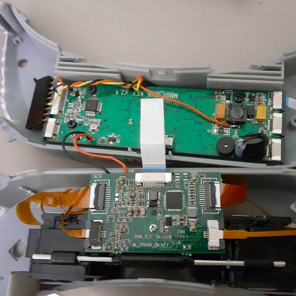
Next up is to unscrew the main goggle PCB. This is the board located on the upper half of goggles. The one lower is the LCD driver, which we will not be using for this mod. There are a few critical areas that need to be available for soldering on the back side, namely the video input and some power outputs.
Finally, pry the two receiver modules and their ribbon cables out of the goggles. These may either be thrown away or saved for future use.
On a side note, it’s worth noticing the good ol’ STM processor in the goggles 🙂
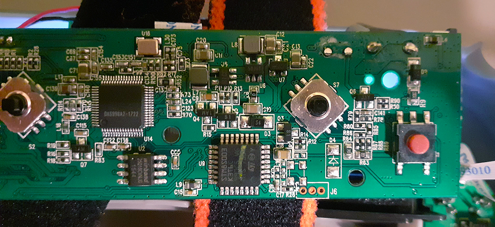
Before we start soldering, it’s a good idea to understand what’s going on in the goggles. The two original individual receivers make up what’s called a diversity FPV system. This means that the goggle will select whichever video signal is stronger, and the receiver with a higher RSSI value (signal strength indicator) is the one selected to be shown to the pilot on their screen. What we are doing to get our custom receiver to output its video signal to the goggles is directly soldering the receiver’s video output to the video input of the goggles, rather than having two receivers. The diversity system is still preserved, as all the switching, comparing, (and in the case of other modules, signal fusion) is done within the module itself.
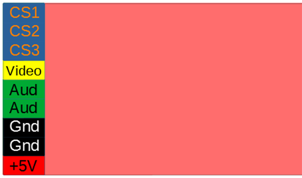
There are nine pins on a standard FPV receiver. The main ones to focus on are the power and video pins. Going from bottom to top, 5V is pin 1, ground are pins 2 and 3, and video output is 6. To connect the receiver to the goggles, I used a nine-pin female header, which allows for easy module installation.
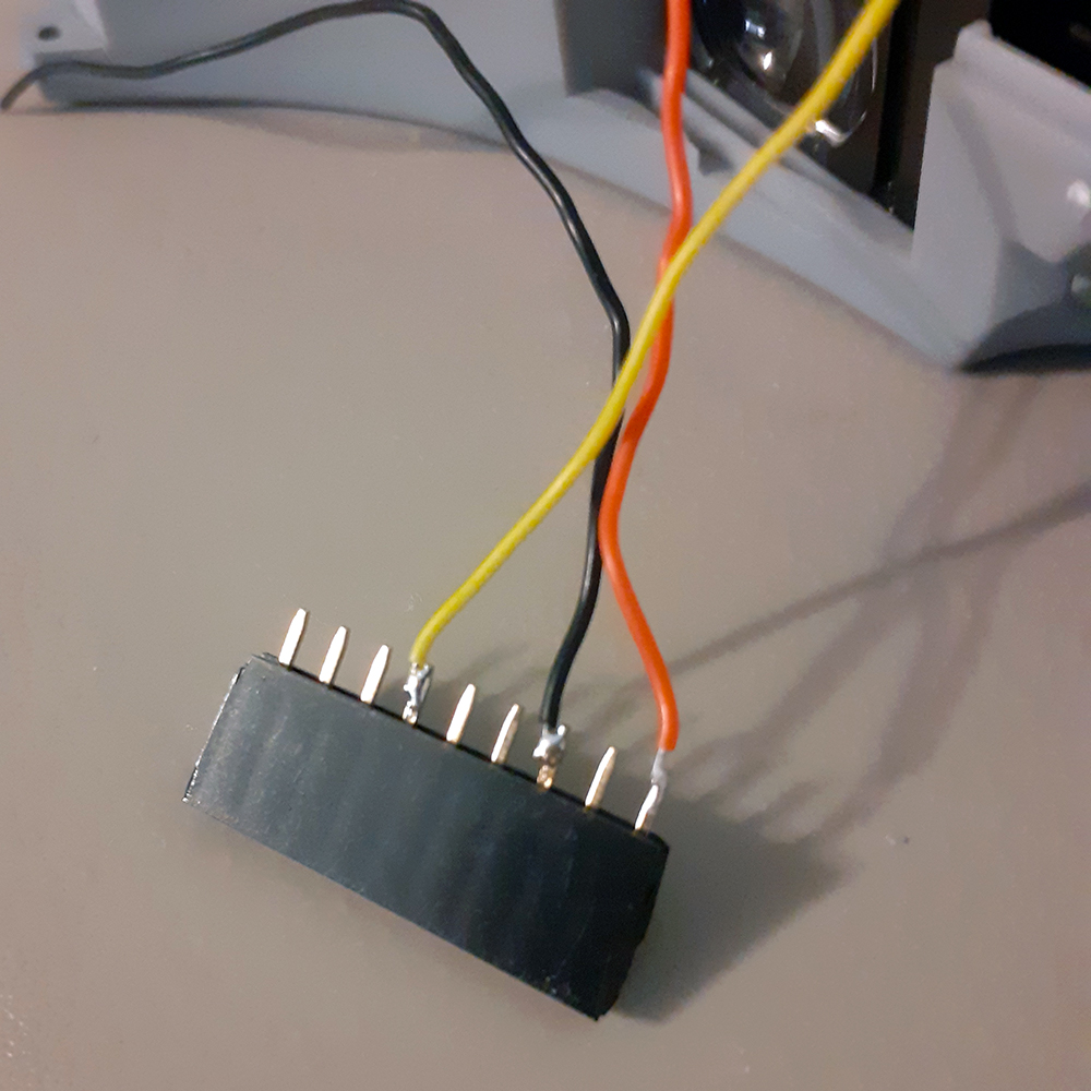
 The actual video input on the goggles was difficult to find, but after some oscilloscope probing and testing, the video input was found to be in the upper left-hand corner of the main board. The pin to solder the video input is the far-right pin on the lower video signal IC.
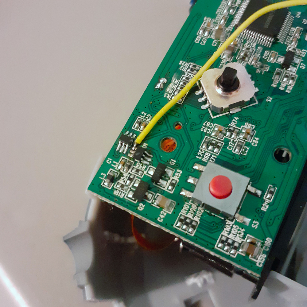
Now, any video signal going through this wire will be displayed to the goggles. However, the receiver module obviously needs power in order to function which is relatively simple. Below in red and black are the recommended pads providing 5V, alongside the black highlighted ground pad.
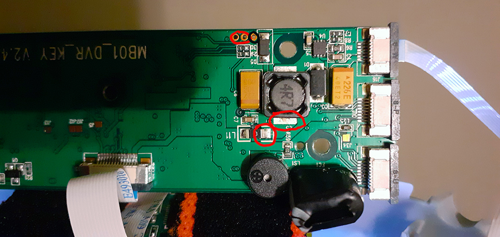
Once the header is all done, you can test out the receiver by plugging it into the header and powering up the goggles. You should be brought immediately to the module’s output. If not, check wiring, voltages, and solder joints to make sure everything is working correctly.
Installing the Module
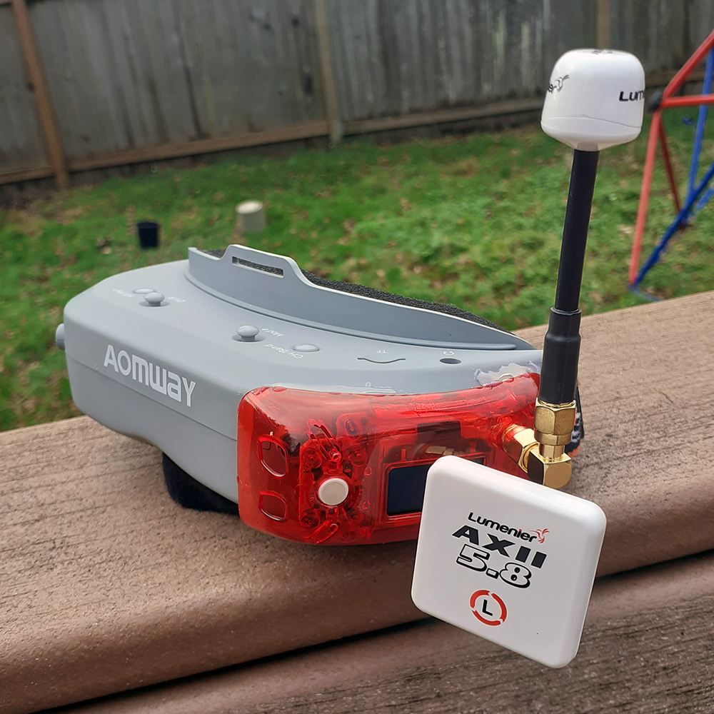
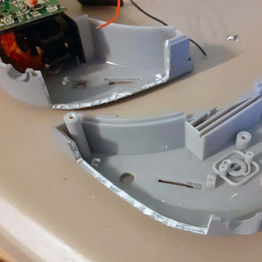
Physically installing the goggle module is probably the hardest part of this project. I used pliers and an X-Acto knife to clean out a cavity in the goggles to allow for fitment of my True-D. Also, I had to cut off some plastic from my True-D’s case to make it fit. In the end, I had to settle with mounting the receiver upside down, but it still worked out great! I used hot glue to seal everything in place and installed my FPV antennas. My favorite ones are the Lumenier Axii 2 because they give excellent range and are relatively lightweight.
Wrapping Up
Now, you may simply re-assemble your Aomway Commander, taking care to not damage the video receiver wires. This is relatively simple, only requiring a few screws to be put back into place.
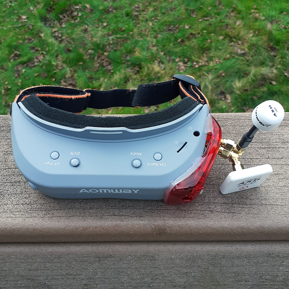
What comes next is up to you! Maybe there can be a way to install the DVR board back. Or include a separate video output for monitors. The possibilities are endless!



Hello… Great post… Thanks for this help!!!!😉
One more question.. does it work with a tbs fusion?
Thanks
Yannick,
In theory, this should work with a TBS Fusion since most modules have a consistent pinout (plug-in modules, that is).
One thought!
Why you need to remove / cut plastic. Can’t you just use AVin port off he googles (+2 supply wires)to feed video out from the Module?
Instead of ripping out any plastic cant we just use the google’s AVin input to feed the module Video signal?
Hey,
I was wondering if this mod would be possible on a commander v2.
Thanks