Congratulations! You’ve worked out your first design and you’re ready to get it manufactured. Maybe you’ve followed our design tutorial, a youtube guide, or just felt your way through it. Whatever it is, congratulations on making a design, and working through the process of getting it cut. Here are some tips, links, and general knowledge to speed you along on your journey to holding your design IRL.
This article was submitted through the GetFPV Community Program by Kai Lin. You can follow Kai on Instagram.
Disclaimer: This article was written solely by a member of the FPV Community. Views and advice in this article are that of the author and does not necessarily reflect the opinion or views of GetFPV.
Preparing Your Designs

3D model to 2D drawing
Depending on what software you use, the method for taking a 2D drawing from your 3D model might be different. However, in the end, the file that you need to end up with is a .DXF file. Many modeling softwares have guides for how to get a 2D .dxf from your 3D model, so be sure to check the guides and tutorials. Here, I will show you how to get a .dxf file from your 3D design in Autodesk’s Fusion360.
In this demonstration, we will be using an arm and export it into a .dxf, the preferable format for CNC.
Getting a clean sketch
The first thing to do is to make a new, clean sketch of the part. Using the project tool under the create toolbar, project the surface of your part, turning off the Projection Link checkbox if it’s on.

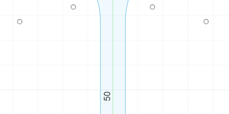
When the part is hidden, your sketch should look like this— blue lines with an inner profile to the arm. The next thing we need to do is make sure the angle is correct. For multipart frames with independent arms, all parts should be at a 90° angle, as seen above. For unibody frames, the best orientation is aligning the arms at a 90° angle, or as close as that can be for a stretched or compressed X frame.
The last part of this sketch is making sure the points and lines are fixed. This way we can make sure that our design is protected from accidental editing. Go to constraints and choose fix/unfix, the function with the lock icon.
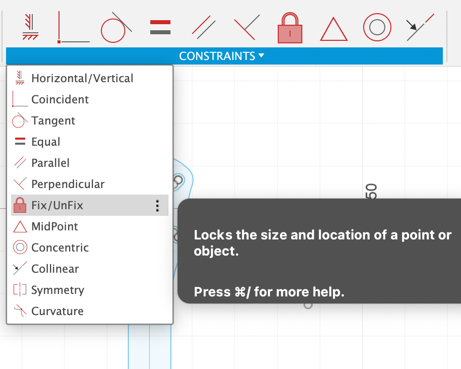
Drag a selection window, covering all points and lines of your sketch.

Once you have done this, all the points and lines should be green, like this. Make sure that there are no additional lines or accidental points in the sketch, and you are good to go! Finish the sketch, and rename it for easy access later.
Exporting the sketch as a DXF
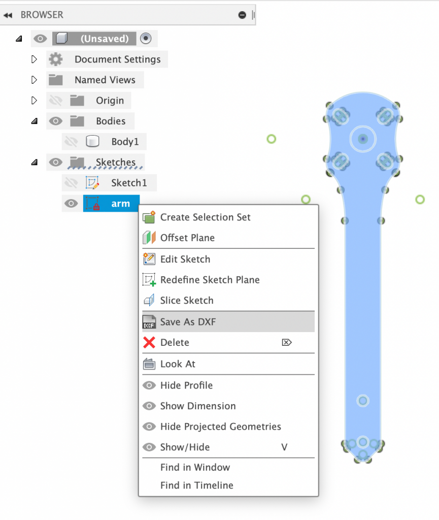
Right click your sketch under the browser tab, and go down to Save As DXF. It’s that easy! Now, different places have different naming conventions. I find that the best universal naming scheme is “(part name)_(thickness)_(special instructions if any).” In our case, that would be “arm_4mm.” If we were to chamfer this arm, it would be named “arm_4mm_w/CH.”
Congratulations! You now have a part ready for cutting. It is recommended to upload your file into a viewer or reupload it into your design program so that you can make sure all lines and points are present in the design, and also that there are no accidental or random lines. https://beta.sharecad.org/ is a good resource for checking this. Great job! You are now ready to get your design cut.
Mechanical Limitations and Design Requirements
Minimum radius

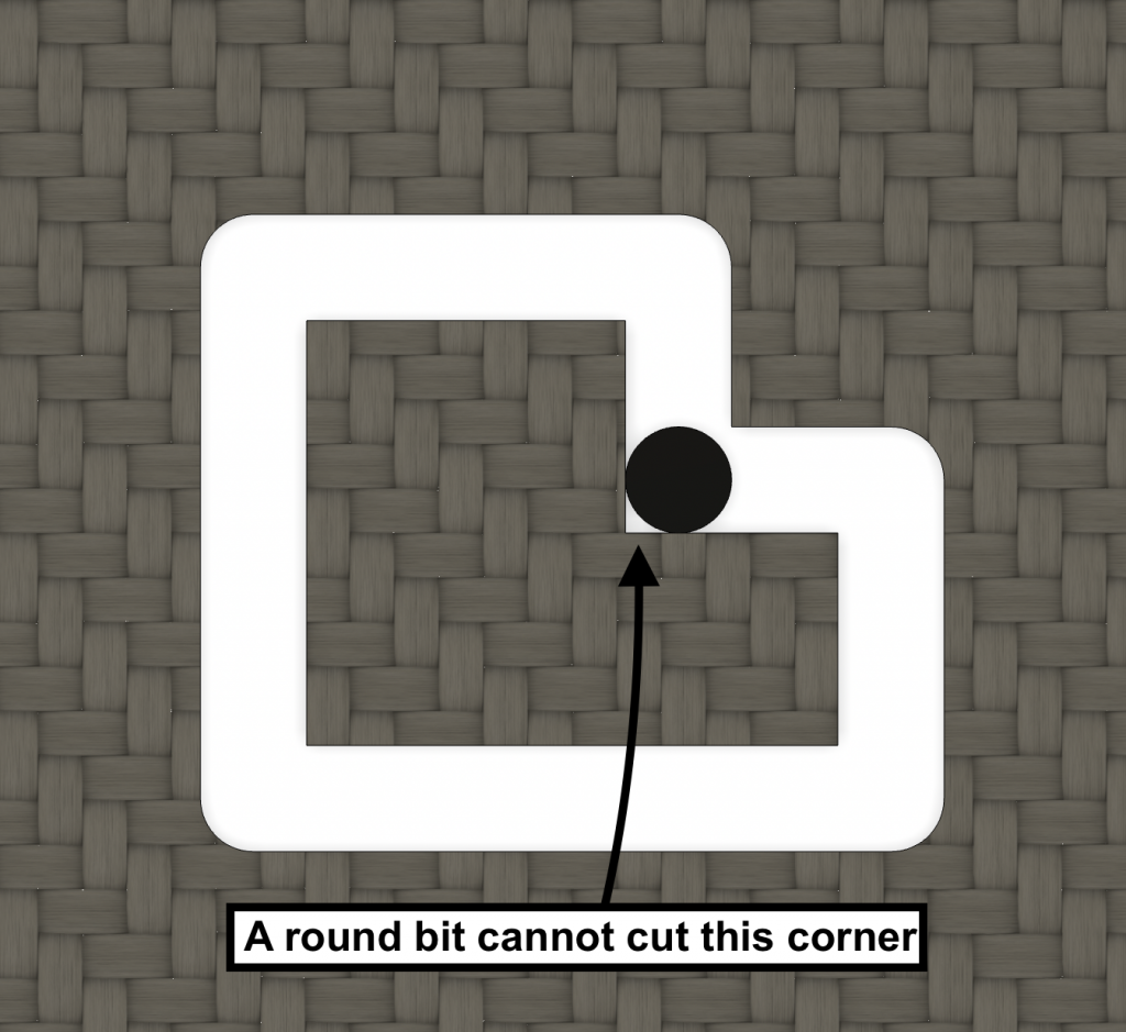
Cnc routers (the machines used to cut) use circular end mills of varied diameter (shown above). Because of this, all inside radii (fillets, rounds, slots, and holes) must be ½ the diameter of the bit used. Inside corners and curves cannot be straight, sharp angles like as seen in the picture below. However, outside curves can be sharp. A design with an inner angle of 90 d would result in an actual part like the image below.
Different services use different sized end mills. For example, CNCmadness (a canadian cnc cutter) uses a 1/16” bit as their standard, so all radii are recommended to be made .8mm or bigger (1/16” ≈ 1.6mm, 1.6mm/2 = .8mm). Armattan productions state the minimum radius can be .5mm, meaning the smallest end mill that they use is 1mm in diameter.
A lot of FPV CNC services use bits 2mm in diameter or smaller, as m2 holes (2mm) are a common size for frames. I recommend making all your radii 1mm or bigger as a general practice if you don’t know your service’s end mill size or will be experimenting with different cutters, but it is always a good idea to check in with your manufacturer to see what size end mills they use.
Dogbones
Ever notice the slots that vertical plates go into look like a bone? Thats because of the mechanical limitation of CNC machines as talked about earlier—all inside cuts have a radius. Because of this, “dogbones” have become a common design practice to ensure parts interlock tightly and properly.
This here is a dogbone. To add them to your designs, all you have to do is add a half circle to the sides of the slots, with a radius of ½ the bit diameter. Super simple, but makes sure that parts can fit. Add them!
Chamfering

Chamfering is a nice addition to your parts to give it that premium look and feel, as well as having practical benefits. Chamfering is creating a 45° angle on an edge, as seen in the design below and arm above. It is most commonly done on arms only, but can be utilized on all types of parts.
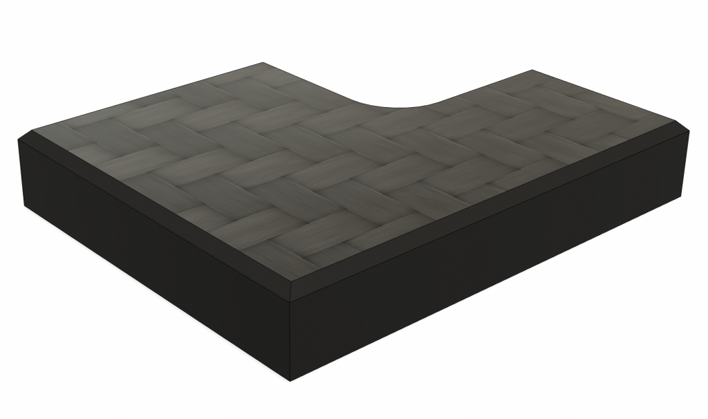
Most 3D design programs have a chamfer function, where you can select an edge, and the amount of chamfer you want. Armattan productions states that .5mm is their default chamfer, and personally that is the size that I like. However, you can play around with it. Different manufacturers like chamfering represented in different ways, so always check in with support or the FAQ when exporting files.
Good Services
CNC madness
Canadian CNC shop, specializing in FPV and carbon fiber. Highly recommended for American and Canadian designers.
- Right on the Canada/America border, and as stated on their site, they “walk all packages across the border and have them imported so that they are then a domestic shipment” so shipping is fast and you avoid fees (CNCmadness).
- Super helpful to talk to. They respond fast via email, and can answer a lot of questions you have.
- Very experienced— super knowledgeable and does precise, fast work. You know how you are supposed to settle with picking 2 out of good, fast, and cheap? Not here. Good, precise cuts, decent turnaround time, and affordably priced.
- Can accommodate single parts, or batches of frames.
- Carry a bunch of types of materials, and hardware. Check out their website for more info on what they carry, cncmadness.com
Armattan Productions
Taiwanese frame on-demand manufacturing company. Sister to Armattan quads who produce their loved lifetime warranty frames. Also a site to sell frames that get cut on-demand.
- Most knowledgeable FPV-oriented CNC company. Years of experience, and are one of the if not most well known and supported frame designers and cutters.
- Low cost
- Easy quote process, and the ability to sell designs from their website at no cost to you. Setup your markup and all needed parts and sit back and relax! No need for inventory to sell frames, and affordable cost gives you options for wider margins or cheap open source parts.
- Reliable and reputable customer support
- Long processing and cutting times, as well as shipping times (coming from Taiwan)
- Please note there is NOT a lifetime warranty on frames ordered and cut through Armattan Productions.
Conclusion
Holding your designs in your hand is an incredible experience. With free design software and low cost manufacturers, it is the perfect time to design and cut your very own frame. Who knows? Maybe your frame will be the next one featured on GetFPV!



Great info! I’ve been thinking about making my own frame and this is very helpful. Thanks!