

[vc_row][vc_column][vc_column_text]The Lumenier Chief Racing Quadcopter is a sleek, lightweight, and durable frame designed through a collaboration with Lumenier and one of the top FPV racers, Alex “Chief” Campbell. It’s designed as a no frills, all performance frame with just the essentials to keep your race day amazing. Thick and easy swap arms will keep you in the heats longer. Coming in at a very affordable price, you can build numerous identical model to craft your racing fleet!
Let’s walk through building the Chief, and we’re going to be using the new Lumenier LUX Mini F7 stack and the durable and lightweight Lumenier ZIP motors. I’ve selected 2750kv motors for a screaming 4S setup.[/vc_column_text][/vc_column][/vc_row][vc_row][vc_column][vc_column_text]
Component List
All parts used for this list are available on the GetFPV store! I have included links that will take you directly to each product, but keep in mind, building a quadcopter is a personal thing! Don’t hesitate to use a different component, and make it your own![/vc_column_text][/vc_column][/vc_row][vc_row][vc_column width=”1/6″][/vc_column][vc_column width=”2/3″][vc_single_image image=”5841″ img_size=”full” alignment=”center” onclick=”link_image”][/vc_column][vc_column width=”1/6″][/vc_column][/vc_row][vc_row][vc_column][vc_column_text]
Lumenier Chief Quadcopter Frame
[/vc_column_text][vc_row_inner][vc_column_inner width=”1/3″][vc_single_image image=”5790″ img_size=”medium” alignment=”center” onclick=”link_image”][/vc_column_inner][vc_column_inner width=”2/3″][vc_column_text]An ultra-light FPV racing airframe designed to give you the winning edge at the track. The Lumenier Chief Racing frame has the perfect blend of weight and durability for top performance. Designed in collaboration with one of the top FPV Racing pilots in the world, Alex Campbell, AKA “Chief”. If you’re looking for a quality airframe to build your racing fleet, this is the one![/vc_column_text][dt_default_button link=”url:https%3A%2F%2Fwww.getfpv.com%2Flumenier-chief-racing-quadcopter.html||target:%20_blank|” size=”medium” button_alignment=”btn_center”]Get the Lumenier Chief Quadcopter Frame[/dt_default_button][/vc_column_inner][/vc_row_inner][vc_separator][vc_column_text]
Lumenier LUX Mini F7 20×20 Stack
[/vc_column_text][vc_row_inner][vc_column_inner width=”1/3″][vc_single_image image=”5794″ img_size=”medium” alignment=”center” onclick=”link_image”][/vc_column_inner][vc_column_inner width=”2/3″][vc_column_text]The powerful F7 flight controller allows for simultaneous processes to be handled with ease, giving you a stable and clean signal to your sensors. The 2-6S 30A ESC features the latest gen. BLHeli_32 firmware running alongside an additional F3 processor to give you even more headroom. Tie it all together with a Smart Audio enabled VTX, capable of 5 variable transmitting powers from PIT, up to 800mW.[/vc_column_text][dt_default_button link=”url:https%3A%2F%2Fwww.getfpv.com%2Flumenier-lux-mini-f7-20×20-stack.html||target:%20_blank|” size=”medium” button_alignment=”btn_center”]Get the Lumenier LUX Mini F7 20×20 Stack![/dt_default_button][/vc_column_inner][/vc_row_inner][vc_separator][vc_column_text]
Lumenier ZIP 2207 2750kv Motors
[/vc_column_text][vc_row_inner][vc_column_inner width=”1/3″][vc_single_image image=”5796″ img_size=”medium” alignment=”center” onclick=”link_image”][/vc_column_inner][vc_column_inner width=”2/3″][vc_column_text]The new ZIP Motor by Lumeneir has been designed and built for incredible performance and power. Rated at 2750kv, this motor hits the sweet spot for screaming 4s (5″ prop) multirotors. The ZIP motors feature top of the line components and powerful N52SH (high temperature) curved magnets for maximum power. This gives you the best performing motor for your racing or freestyle drone.[/vc_column_text][dt_default_button link=”url:https%3A%2F%2Fwww.getfpv.com%2Flumenier-zip-2207-2750kv-motor.html||target:%20_blank|” size=”medium” button_alignment=”btn_center”]Get the Lumenier ZIP 2207 2750kv Motor![/dt_default_button][/vc_column_inner][/vc_row_inner][vc_separator][vc_column_text]
RunCam Micro Eagle – Lumenier Edition
[/vc_column_text][vc_row_inner][vc_column_inner width=”1/3″][vc_single_image image=”5793″ img_size=”medium” alignment=”center” onclick=”link_image”][/vc_column_inner][vc_column_inner width=”2/3″][vc_column_text]The shrinking FPV Camera trend continues with RunCam’s newest addition to the micro series, the Eagle Micro! The Eagle Micro takes all of the amazing specs of the Eagle and has stuffed them in a tiny 8.9g camera. The Eagle Micro includes all the features such as 6 levels of adjustable WDR and switchable 4:3 or 16:9 aspect ratio – even the same M12 lens, giving you amazing clarity rarely found in a micro camera![/vc_column_text][dt_default_button link=”url:https%3A%2F%2Fwww.getfpv.com%2Fruncam-micro-eagle-lumenier-edition-white.html||target:%20_blank|” size=”medium” button_alignment=”btn_center”]Get the RunCam Micro Eagle – Lumenier Edition[/dt_default_button][/vc_column_inner][/vc_row_inner][vc_separator][vc_column_text]
Lumenier Micro AXII Straight MMCX 5.8GHz Antenna
[/vc_column_text][vc_row_inner][vc_column_inner width=”1/3″][vc_single_image image=”5795″ img_size=”medium” alignment=”center” onclick=”link_image”][/vc_column_inner][vc_column_inner width=”2/3″][vc_column_text]Even though the Micro AXII is both small and lightweight, it does not sacrifice on performance. The Micro AXII is designed to be ultra durable and put up with the beatings FPV pilots put on their antennas. The antenna array is securely protected inside the injection molded casing. The outer shell case is made from an impact resistant poly-carbonate material, and is sealed shut to guard the antenna elements.[/vc_column_text][dt_default_button link=”url:https%3A%2F%2Fwww.getfpv.com%2Flumenier-micro-axii-straight-mmcx-5-8ghz-antenna-rhcp.html||target:%20_blank|” size=”medium” button_alignment=”btn_center”]Get the Lumenier Micro AXII Straight MMCX 5.8GHz Antenna![/dt_default_button][/vc_column_inner][/vc_row_inner][vc_separator][vc_column_text]
Team Blacksheep Crossfire Nano Rx
[/vc_column_text][vc_row_inner][vc_column_inner width=”1/3″][vc_single_image image=”5791″ img_size=”medium” alignment=”center” onclick=”link_image”][/vc_column_inner][vc_column_inner width=”2/3″][vc_column_text]TBS is stepping up the Long Range / UHF game, with no competition in sight! With the TBS Crossfire Nano RX, we condense two years of engineering experience, listening to our customer requirements, and pushing ourselves to the maximum (or in this case, the minimum!). The end result is a full range receiver, at the smallest size of any receiver in the industry (yes, it’s smaller than the XM+).[/vc_column_text][dt_default_button link=”url:https%3A%2F%2Fwww.getfpv.com%2Ftbs-crossfire-nano-rx.html||target:%20_blank|” size=”medium” button_alignment=”btn_center”]Get the TBS Crossfire Nano Rx![/dt_default_button][/vc_column_inner][/vc_row_inner][vc_separator][vc_column_text]
Team Blacksheep Crossfire Immortal T Antenna V2
[/vc_column_text][vc_row_inner][vc_column_inner width=”1/3″][vc_single_image image=”5792″ img_size=”medium” alignment=”center” onclick=”link_image”][/vc_column_inner][vc_column_inner width=”2/3″][vc_column_text]TBS has improved the signal sensitivity and durability of the Immortal T antenna. The center housing is made from rubberized plastic material which allows a degree of bending to minimize damage from crashes. The spring-steel element has the same immortality from V1 which will protect itself from prop-strikes and incorrect mounting. Further tuning on the center element provides better coverage and range.[/vc_column_text][dt_default_button link=”url:https%3A%2F%2Fwww.getfpv.com%2Ftbs-crossfire-immortal-t-antenna-v2.html||target:%20_blank|” size=”medium” button_alignment=”btn_center”]Get the TBS Crossfire Immortal T Antenna V2![/dt_default_button][/vc_column_inner][/vc_row_inner][vc_separator][vc_column_text]
DAL Cyclone T5050C Pro Propellers
[/vc_column_text][vc_row_inner][vc_column_inner width=”1/3″][vc_single_image image=”5842″ img_size=”medium” alignment=”center” onclick=”link_image”][/vc_column_inner][vc_column_inner width=”2/3″][vc_column_text]The Cyclone T5050C Pro Tri-Blade 5″ Props by DAL are an upgraded version of the Cyclone T5050C Series. These propellers feature faster cornering, less noise, and an excellent aerodynamic design! DALProps has been a mainstay in the prop industry for a long time, and their Cyclone series is well known as some of the most dependable props on the market. DALprops are fast, durable and excellent props for racing![/vc_column_text][dt_default_button link=”url:https%3A%2F%2Fwww.getfpv.com%2Fdal-cyclone-t5050c-pro-propellers-set-of-4.html||target:%20_blank|” size=”medium” button_alignment=”btn_center”]Get the DAL Cyclone T5050C Pro Propellers[/dt_default_button][/vc_column_inner][/vc_row_inner][/vc_column][/vc_row][vc_row][vc_column][vc_column_text]
The Lumenier Chief Build
The Lumenier Chief is a very tight, no frills racing frame. It has only what you need, and nothing else. However, It is light, durable, and capable of taking either a 20×20 stack or a 30.5 x 30.5 stack. It features quick replace arms as well. It’s not an overly complicated build, but there are a few gotcha moments that we will cover in depth. We are going to be focusing on a clean build as the space in the frame is quite limited.[/vc_column_text][/vc_column][/vc_row][vc_row][vc_column width=”1/2″][vc_column_text]
Required Tools:
- Soldering Iron
- Side Cutters (Wire Cutters)
- 2mm Hex Driver
- 1.5mm Hex Driver
- Heat Gun
- 8mm Nut Driver or Prop Wrench
- 5.5mm Nut Driver
- 3D Printer (or access to one)
[/vc_column_text][/vc_column][vc_column width=”1/2″][vc_column_text]
Extra Build Materials:
- Heat Shrink
- Zip Ties (Small)
- Electrical Tape
- TPU Filament for 3D Printer
- 14AWG Wire
- XT60 Connector
[/vc_column_text][/vc_column][/vc_row][vc_row][vc_column width=”1/6″][/vc_column][vc_column width=”2/3″][vc_single_image image=”5844″ img_size=”full” alignment=”center” onclick=”link_image”][/vc_column][vc_column width=”1/6″][/vc_column][/vc_row][vc_row][vc_column][vc_column_text]
Building the Lumenier Chief Frame Base
Parts Needed:
- Lumenier Chief carbon fiber frame and hardware
- One Lumenier ZIP 2207 2750kv Motor (or your motor of choice)
Tools Needed:
- 2mm Hex Driver
[/vc_column_text][/vc_column][/vc_row][vc_row][vc_column][vc_separator el_width=”60″][/vc_column][/vc_row][vc_row][vc_column][vc_column_text]For this first part of the build, we are going to be focusing on just the bottom portion of the frame. The specific parts you will need include:
- Bottom Plate
- Mid Plate
- Arms
- 30mm screws
- 8mm screws
[/vc_column_text][/vc_column][/vc_row][vc_row][vc_column width=”1/6″][/vc_column][vc_column width=”2/3″][vc_single_image image=”5846″ img_size=”full” alignment=”center” onclick=”link_image”][/vc_column][vc_column width=”1/6″][/vc_column][/vc_row][vc_row][vc_column][vc_column_text]Before we begin building the frame, we need to figure out which side of the arm is the upper side. I know this sounds like a silly thing, but it is one of the strange things about this frame. The easiest way to sort this out is to use a motor, and either line up the holes to the motor mount, or physically attach the motor to the arm.
When mounted correctly, you will notice that the wires coming from the motor align with the arm. It’s very obvious when it’s wrong. If you discover one that is incorrect, just flip it over. See the images below for an example.[/vc_column_text][/vc_column][/vc_row][vc_row][vc_column width=”1/2″][vc_single_image image=”5848″ img_size=”full” alignment=”center” onclick=”link_image”][/vc_column][vc_column width=”1/2″][vc_single_image image=”5847″ img_size=”full” alignment=”center” onclick=”link_image”][/vc_column][/vc_row][vc_row][vc_column][vc_column_text]With that taken care of, let’s move on to the bottom and mid plates!
- The bottom plate is the small clover leaf plate while the mid plate is the large plate with the press nuts in it.
20 x 20 Stack
Step 1: If you are using a 20×20 stack like I am, then place the 30mm screws through the inner hole of clover and align it with the same hole on the mid plate. These screws will make up your stack mounts.
Step 2: Screw in the 30mm screws about 75% of the way, and leave about a 6mm gap between the mid plate and base plate.[/vc_column_text][/vc_column][/vc_row][vc_row][vc_column width=”1/6″][/vc_column][vc_column width=”2/3″][vc_single_image image=”5850″ img_size=”full” alignment=”center” onclick=”link_image”][/vc_column][vc_column width=”1/6″][/vc_column][/vc_row][vc_row][vc_column][vc_column_text]Step 3: Slip each of the arms into the gap between the two plates, ensuring that the points of the arms are facing forward and backward, and that the right side of the arm is facing up toward the mid plate.
Step 4: Tighten the 30mm screw 95% of the way after inserting each arm, just enough to hold it roughly in place.
Step 5: Insert the 8mm screw into the outer hole to retain the arm in position.
Step 6: Complete all the arms, then secure all screws tightly.[/vc_column_text][/vc_column][/vc_row][vc_row][vc_column width=”1/6″][/vc_column][vc_column width=”2/3″][vc_single_image image=”5854″ img_size=”full” alignment=”center” onclick=”link_image”][/vc_column][vc_column width=”1/6″][/vc_column][/vc_row][vc_row][vc_column][vc_column_text]
30.5 x 30.5 Stack
If you are using a 30.5mm stack, then you will reverse where the 30mm and 8mm screws are. You would start with the 8mm screw on the inner hole, and only tighten it for a turn or two. Insert the arm, then secure it with the 30mm screw on the outer hole.
Note: While you can build either, the 20mm stack is more effective for being able to swap an arm quickly, as you will not need to pull out a stack screw to release the arm.
Step 7: Use one more 8mm screw in the center hole to tighten the plates together to create a pinch point to better secure the arms.[/vc_column_text][/vc_column][/vc_row][vc_row][vc_column width=”1/6″][/vc_column][vc_column width=”2/3″][vc_single_image image=”5856″ img_size=”full” alignment=”center” onclick=”link_image”][/vc_column][vc_column width=”1/6″][/vc_column][/vc_row][vc_row][vc_column][vc_column_text]
Pin-out Diagram
Now that we’re going to be getting into soldering, understanding what goes where will be critical. I will fully explain each connection below, but you can use this as a reference if you need some clarification![/vc_column_text][/vc_column][/vc_row][vc_row][vc_column width=”1/6″][/vc_column][vc_column width=”2/3″][vc_single_image image=”5915″ img_size=”full” alignment=”center” onclick=”link_image”][/vc_column][vc_column width=”1/6″][/vc_column][/vc_row][vc_row][vc_column][vc_column_text]
Motors and 4-in-1 ESC
Parts Needed:
- Lumenier ZIP 2207 2750kv Motors (4)
- Lumenier Micro Razor 4in1 20×20 F3 BLHeli_32 30A 2-6s ESC (From Stack Kit)
- Motor Screws from Lumenier Chief Frame Kit (12)
- Short standoffs from Lumenier LUX Mini F7 Flight Controller hardware kit (4)
Tools Needed:
- 2mm Hex Driver
- Soldering Iron
- Side Cutters
- Electrical Tape
[/vc_column_text][/vc_column][/vc_row][vc_row][vc_column][vc_separator el_width=”60″][/vc_column][/vc_row][vc_row][vc_column][vc_column_text]Step 1: Mount all four motors on the arms using the screws from the Lumenier Chief hardware pack.
Step 2: Take the four (4) short standoff’s from the Lumenier LUX Mini F7 Flight Controller hardware pack and drop them on the stack screws.
Step 3: Test mount the Lumenier Micro Razor 4-in-1 ESC by placing it on the stack screws. Make sure the Lumenier logo and motor number designations are facing up. This will keep the motor order correct.[/vc_column_text][/vc_column][/vc_row][vc_row][vc_column width=”1/2″][vc_single_image image=”5857″ img_size=”full” alignment=”center” onclick=”link_image”][/vc_column][vc_column width=”1/2″][vc_single_image image=”5858″ img_size=”full” alignment=”center” onclick=”link_image”][/vc_column][/vc_row][vc_row][vc_column][vc_column_text]Step 4: Tin (add solder) to all the motor pads and the power lead pads on the ESC. Place the ESC on the stack if you removed it. The side with the power lead tabs will be the rear of the aircraft.
Step 5: Decide how you want you route your route your motor wires to your ESC. Routing them on the outside makes it much easier to replace the motor if they are damaged. Routing them on the inside protects them a little better in the event of a crash.[/vc_column_text][/vc_column][/vc_row][vc_row][vc_column width=”1/6″][/vc_column][vc_column width=”2/3″][vc_single_image image=”5861″ img_size=”full” alignment=”center” onclick=”link_image”][/vc_column][vc_column width=”1/6″][/vc_column][/vc_row][vc_row][vc_column][vc_column_text]Step 6: Tame those unruly motor wires with a few wraps of electrical tape. The closer you tape them wires toward the body, the easier they will be to manage.
Step 7: Measure out each wire to the corresponding pad. It does not matter which wire goes to which pad on that corner, just make sure you use the three closest tabs for each motor. If there is an issue with motor direction, we can fix that later in the BL_Heli Suite.[/vc_column_text][/vc_column][/vc_row][vc_row][vc_column width=”1/6″][/vc_column][vc_column width=”2/3″][vc_single_image image=”5862″ img_size=”full” alignment=”center” onclick=”link_image”][/vc_column][vc_column width=”1/6″][/vc_column][/vc_row][vc_row][vc_column][vc_column_text]Step 8: Cut each wire to the appropriate length, strip about 3mm from the end of each wire. Twist and tin the exposed ends of the wire then solder them to the tab.
Step 9: Complete this for each motor, ensuring the solder joints are complete and free from short circuits. Use electronics parts cleaner (99.9% Isopropyl Alcohol) to clean the joints of rosin flux if you so choose. Flux can act as a corrosive over an extended period of time.[/vc_column_text][/vc_column][/vc_row][vc_row][vc_column width=”1/6″][/vc_column][vc_column width=”2/3″][vc_single_image image=”5863″ img_size=”full” alignment=”center” onclick=”link_image”][/vc_column][vc_column width=”1/6″][/vc_column][/vc_row][vc_row][vc_column][vc_column_text]
XT-60 Power Lead
Parts Needed:
- XT-60 Connector (Male and Female)
- 14AWG Silicone Wire
- Heat Shrink Tubing (3/16″)
Tools Required:
- Side Cutters
- Soldering Iron
- Heat Gun
- Rosin Flux Pen or Rosin Flux Liquid
[/vc_column_text][/vc_column][/vc_row][vc_row][vc_column][vc_separator el_width=”60″][/vc_column][/vc_row][vc_row][vc_column][vc_column_text]Step 1: Take both the male and female XT-60 connectors (male would be the power lead side, while female would be the battery connector side) and combine them together. This will help protect the male connector when you solder the power wire.
Step 2: Cut your power lead wires to approximately 90mm. This will give you good reach to the battery.[/vc_column_text][/vc_column][/vc_row][vc_row][vc_column width=”1/2″][vc_single_image image=”5869″ img_size=”full” alignment=”center” onclick=”link_image”][/vc_column][vc_column width=”1/2″][vc_single_image image=”5870″ img_size=”full” alignment=”center” onclick=”link_image”][/vc_column][/vc_row][vc_row][vc_column][vc_column_text]Step 3: Strip 8mm from one end of each of the power wires and twist the ends. This side will being going inside the male connector wire wells. Twist the exposed wires, add flux, and tin the wires.
Note: Adding flux is not necessary if you don’t have it, but with this wire being especially thick, it helps the heat flow more evenly as well as enhances solder flow. Consider raising the temperature of your soldering iron from this step, all the way through Step 8. (I use 750° F or 400° C)
Step 4: Add a little bit of solder to each of the connectors on the XT-60, then solder in each power lead.[/vc_column_text][/vc_column][/vc_row][vc_row][vc_column width=”1/6″][/vc_column][vc_column width=”2/3″][vc_single_image image=”5871″ img_size=”full” alignment=”center” onclick=”link_image”][/vc_column][vc_column width=”1/6″][/vc_column][/vc_row][vc_row][vc_column][vc_column_text]Step 5: Cut two pieces of 3/16″ heat shrink at about 20mm, slide them on to the power leads, and use the heat gun (or lighter) to shrink down the ends slightly on the connector side. This will allow you to slide the heat shrink up over the XT-60 wire connectors.
Step 6: Cut 4mm from the other ends of the power lead wires, flux, and tin them. Solder them to the ESC, ensuring to match up the positive side to the positive pad, and ground side to the ground pad.[/vc_column_text][/vc_column][/vc_row][vc_row][vc_column width=”1/2″][vc_single_image image=”5872″ img_size=”full” alignment=”center” onclick=”link_image”][/vc_column][vc_column width=”1/2″][vc_single_image image=”5873″ img_size=”full” alignment=”center” onclick=”link_image”][/vc_column][/vc_row][vc_row][vc_column][vc_column_text]
Flight Controller
Parts Needed:
- Lumenier LUX Mini F7 Flight Controller
- ESC to FC Cable Harness
- Tall standoffs from Lumenier LUX Mini F7 Flight Controller hardware pack
Tools Required:
- Soldering Iron
[/vc_column_text][/vc_column][/vc_row][vc_row][vc_column][vc_separator el_width=”60″][/vc_column][/vc_row][vc_row][vc_column][vc_column_text]Step 1: Attach the ESC to FC Cable harness to the ESC and the flight controller, ensuring that the connector is oriented correctly.[/vc_column_text][/vc_column][/vc_row][vc_row][vc_column width=”1/6″][/vc_column][vc_column width=”2/3″][vc_single_image image=”5875″ img_size=”full” alignment=”center” onclick=”link_image”][/vc_column][vc_column width=”1/6″][/vc_column][/vc_row][vc_row][vc_column][vc_column_text]Step 2: Place the tall standoffs on the stack screws, then put the flight controller on the stack. Ensuring that the Lumenier logo is up, and that the arrow on the Flight controller is facing forward.
Step 3: The cable will route under the flight controller and will have a single twist in it. There is plenty of room between the ESC and flight controller.[/vc_column_text][/vc_column][/vc_row][vc_row][vc_column width=”1/2″][vc_single_image image=”5876″ img_size=”full” alignment=”center” onclick=”link_image”][/vc_column][vc_column width=”1/2″][vc_single_image image=”5877″ img_size=”full” alignment=”center” onclick=”link_image”][/vc_column][/vc_row][vc_row][vc_column][vc_column_text]Step 4: Tin the following pads on the flight controller: TX3, RX3, 5V, and GND on the side of the flight controller next to the USB connector. We will be using these for the TBS Crossfire Nano.
Step 5: Tin the following pads on the flight controller for use with the FPV Camera and VTX: GND, PWR, S/A (Smart Audio), VTX, CAM, PWR, GND.[/vc_column_text][/vc_column][/vc_row][vc_row][vc_column width=”1/6″][/vc_column][vc_column width=”2/3″][vc_single_image image=”5880″ img_size=”full” alignment=”center” onclick=”link_image”][/vc_column][vc_column width=”1/6″][/vc_column][/vc_row][vc_row][vc_column][vc_column_text]
TBS Crossfire Nano
Parts Needed:
- TBS Crossfire Nano
- Four (4) wires from the TBS Crossfire Nano Accessories
Tools Required:
- Side Cutters
- Soldering Iron
[/vc_column_text][/vc_column][/vc_row][vc_row][vc_column][vc_separator el_width=”60″][/vc_column][/vc_row][vc_row][vc_column width=”1/6″][/vc_column][vc_column width=”2/3″][vc_single_image image=”5881″ img_size=”full” alignment=”center” onclick=”link_image”][/vc_column][vc_column width=”1/6″][/vc_column][/vc_row][vc_row][vc_column][vc_column_text]Step 1: Using the wiring guide above tin to complete the next steps, trim your four wires to 40mm. This will give you plenty of wire to reach the pads on the flight controller when the VTX has been installed.
Step 2: Strip about 2-3mm from each of the four wires, twist and tin the ends. Solder each of the wire to the appropriate pad. I use to following standard: black to ground, red to 5V, white to CH. 1, yellow to CH. 2.[/vc_column_text][/vc_column][/vc_row][vc_row][vc_column width=”1/2″][vc_single_image image=”5882″ img_size=”full” alignment=”center” onclick=”link_image”][/vc_column][vc_column width=”1/2″][vc_single_image image=”5883″ img_size=”full” alignment=”center” onclick=”link_image”][/vc_column][/vc_row][vc_row][vc_column][vc_column_text]Note: I use the through hole method to solder the wires here, with the wires coming from the top (side with the bind button and antenna connector) as when heat shrink is added later, they will lay flat across the Crossfire Nano.
Step 3: Strip about 3mm from the opposite ends of the wires from the Crossfire Nano. Twist and tin the wires, then solder them to the FC, making the following connections:
- Yellow to TX3
- White to RX3
- Red to 5V
- Black to GND.
Solder them with the points of the wires point toward the edge of the board, in order to keep them inside the frame and less susceptible to damage.
Note: Do not attach the antenna at this time, as it will only get in the way as we finish up the rest of the Lumenier Chief build. Also, wait to put the heat shrink on until the antenna is attached, and we have bound the Crossfire Nano.[/vc_column_text][/vc_column][/vc_row][vc_row][vc_column width=”1/6″][/vc_column][vc_column width=”2/3″][vc_single_image image=”5885″ img_size=”full” alignment=”center” onclick=”link_image”][/vc_column][vc_column width=”1/6″][/vc_column][/vc_row][vc_row][vc_column][vc_column_text]
RunCam Micro Eagle FPV Camera & Lumenier LUX Mini VTX
Parts Needed:
- RunCam Micro Eagle – Lumenier Edition
- Lumenier LUX Mini VTX
- Wire harness from Micro Eagle accessories
- Two (2) mounting screws from Micro Eagle accessories
- Four (4) wires from Lumenier LUX Mini VTX accessories
- Lumenier Chief Micro FPV Mount – Fixed 40° 3D Print
- Four (4) O-Rings from Lumenier LUX Mini F7 accessories
- Four (4) Nylon nuts from Lumenier LUX Mini F7 accessories
Tools Required:
- 3D Printer
- Side Cutters
- Soldering Iron
[/vc_column_text][/vc_column][/vc_row][vc_row][vc_column][vc_separator el_width=”60″][/vc_column][/vc_row][vc_row][vc_column][vc_column_text]The Lumenier Chief is designed for a “nano” size camera, such as the RunCam Racer Nano 2, however I choose to go with the larger micro size camera for a little better image quality. In order to make that work you will need to 3D print the camera mount listed above created by QuadMcFly specifically for the Lumenier Chief.
Step 1: Unscrew the lens from the RunCam Micro Eagle and remove the retention ring from the lens. Insert the lens into the 3D Print then screw the retaining ring all the way up to the 3D print area. Screw the camera body back onto the lens and use the mounting screws to secure the 3D print to the camera body. We will focus the camera later.[/vc_column_text][/vc_column][/vc_row][vc_row][vc_column width=”1/6″][/vc_column][vc_column width=”2/3″][vc_single_image image=”5889″ img_size=”full” alignment=”center” onclick=”link_image”][/vc_column][vc_column width=”1/6″][/vc_column][/vc_row][vc_row][vc_column][vc_column_text]Step 2: Cut four (4) of the wires from the VTX accessories to 20mm. Strip 3mm from each side, twist and tin the ends. Solder each wire to the flight controller using the following standard:
- Yellow to VTX
- White to S/A
- Red to PWR
- Black to GND
Step 3: Cut the camera connecting wire to 25mm from where the wires enter the connector. Twist, and tin the ends, and solder them to the flight controller using the following standard:
- Black to GND
- Red to PWR
- Yellow to CAM
[/vc_column_text][/vc_column][/vc_row][vc_row][vc_column width=”1/6″][/vc_column][vc_column width=”2/3″][vc_single_image image=”5890″ img_size=”full” alignment=”center” onclick=”link_image”][/vc_column][vc_column width=”1/6″][/vc_column][/vc_row][vc_row][vc_column][vc_column_text]Step 4: Put the four (4) O-rings on the stack screws, then place the Lumenier LUX Mini VTX on the stack. Put the four (4) plastic nuts on the stack screws to secure the stack. When putting the nuts on, press slightly down on the VTX, as there are components that will get knocked by the nuts if you’re not careful.
Step 5: Tin the following pads on the top of the VTX (The side with all the components):
- GND
- DCIN
- S/A
- VID
Step 6: Loop each of the wires coming from the flight controller up to the VTX and solder using the following standard.
- Black to GND
- Red to DCIN
- Yellow to VID
- White to S/A
[/vc_column_text][/vc_column][/vc_row][vc_row][vc_column width=”1/6″][/vc_column][vc_column width=”2/3″][vc_single_image image=”5891″ img_size=”full” alignment=”center” onclick=”link_image”][/vc_column][vc_column width=”1/6″][/vc_column][/vc_row][vc_row][vc_column][vc_column_text]
Top Plate and Lumenier AXII Mount
Parts Needed:
- Top Plate
- Four (4) 8mm scres
- Four Knurled Standoffs
- Lumenier Chief – Micro AXII Mount 3D Print
- Lumenier Micro AXII
- TBS Immortal T Antenna
- Heat Shrink for Crossfire Nano
Tools Required:
- 3D Printer
- 2mm Hex Driver
- Heat Gun
[/vc_column_text][/vc_column][/vc_row][vc_row][vc_column][vc_separator el_width=”60″][/vc_column][/vc_row][vc_row][vc_column][vc_column_text]Step 1: Build out the top plate assembly by attaching the standoffs via the 8mm screws.
Step 2: 3D Print the Lumenier Chief – Micro AXII Mount listed above which I have created specifically for this project. Insert the Micro AXII into the antenna cup by running the wire through the hole. The mount should hold the Micro AXII snugly.[/vc_column_text][/vc_column][/vc_row][vc_row][vc_column width=”1/6″][/vc_column][vc_column width=”2/3″][vc_single_image image=”5893″ img_size=”full” alignment=”center” onclick=”link_image”][/vc_column][vc_column width=”1/6″][/vc_column][/vc_row][vc_row][vc_column][vc_column_text]Step 3: Slide the AXII Mount and the FPV Camera assembly on to the standoffs, ensuring that the camera is on the front facing side of the plate and camera is pointing up.[/vc_column_text][/vc_column][/vc_row][vc_row][vc_column width=”1/6″][/vc_column][vc_column width=”2/3″][vc_single_image image=”5894″ img_size=”full” alignment=”center” onclick=”link_image”][/vc_column][vc_column width=”1/6″][/vc_column][/vc_row][vc_row][vc_column][vc_column_text]Step 4: Attach the TBS Immortal T antenna to the Crossfire Nano and plug in the Micro AXII to the Lumenier LUX Mini VTX. Plug in the FPV camera into the VTX. Plug a battery into the Lumenier Chief, to begin the power up cycle.
Step 5: Begin the bind and update process for the Crossfire Nano using the Crossfire Nano – Quick Start Guide. Once complete, slide on the heat shrink and use the heat gun to shrink it down. and attach it to the top plate with a zip tie.[/vc_column_text][/vc_column][/vc_row][vc_row][vc_column width=”1/6″][/vc_column][vc_column width=”2/3″][vc_single_image image=”5895″ img_size=”full” alignment=”center” onclick=”link_image”][/vc_column][vc_column width=”1/6″][/vc_column][/vc_row][vc_row][vc_column][vc_column_text]Step 6: Place the top plate assembly on the body of the Lumenier Chief and secure with four (4) 8mm screws in the mid plate.
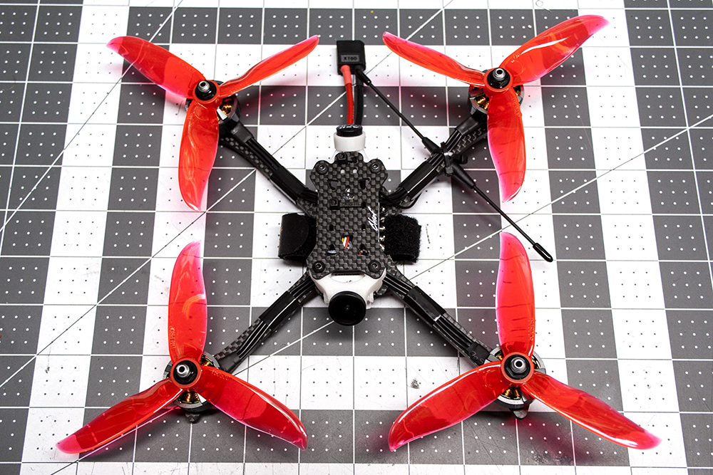
Step 7: While the Lumenier Chief is flipped over, go ahead secure the Immortal T to the arm using two zip ties and attach the battery pad on the bottom plate. Your Lumenier Chief is now complete!
Next up: Betaflight Setup![/vc_column_text][/vc_column][/vc_row][vc_row][vc_column width=”1/2″][vc_single_image image=”5898″ img_size=”full” alignment=”center” onclick=”link_image”][/vc_column][vc_column width=”1/2″][vc_single_image image=”5897″ img_size=”full” alignment=”center” onclick=”link_image”][/vc_column][/vc_row][vc_row][vc_column][vc_single_image image=”5900″ img_size=”full” alignment=”center” onclick=”link_image”][/vc_column][/vc_row][vc_row][vc_column][vc_column_text]
Betaflight Setup
We’re not going to go into depth on Betaflight, but we will cover the basics to get the Lumenier Chief up in the air based on how we built it above.
Ports Tab
Here, we need to setup the UART’s for both the Crossfire Nano and for Smart Audio. If you remember, we soldered the Crossfire Nano to TX3 and RX3, meaning that it will be operatring on UART 3. The Lumenier LUX Mini F7 flight controller comes automatically setup for the receiver on UART 1, so click off the Serial RX there, and click it on for UART 3.
UART 5 is where we will turn on VTX (Smart Audio) under the Peripherals column. This will allow you to control settings for the flight controller and VTX via the transmitter. Check the image below to ensure you have it set up correctly. Make sure to click “Save and Reboot” before moving on to the next tab.
Note: Do not touch the Configuration/MSP column for the USB VCP. This will disable the USB port, making further configuration troublesome.[/vc_column_text][/vc_column][/vc_row][vc_row][vc_column width=”1/6″][/vc_column][vc_column width=”2/3″][vc_single_image image=”5905″ img_size=”full” alignment=”center” onclick=”link_image”][/vc_column][vc_column width=”1/6″][/vc_column][/vc_row][vc_row][vc_column][vc_column_text]
Configuration Tab
Here we have several things that we need to setup. Under ESC/Motor Features, set the ESC Protocol to DSHOT600. Since this is an F7 Chip on the Lumenier LUX Mini, we have the capacity to run a higher GYRO and PID loop frequency. Under System Configuration, set both of those to 8kHz,
In order to get the Crossfire Nano fully functional we need to ensure that the FC is expecting the Crossfire protocol. Under the Receiver section, ensure that the mode is set to serial-based receiver (remember we set that up in the Ports tab). Under Serial Receiver Provider, select CRSF.
Under the Arming section, you can limit the arm angle to keep the quad from arming when it is tilted beyond the specified angle. I set it to 180 to effectively shut it off to allow arming at any angle (useful if you get stuck in a tree). Use the image below to verify you’re set up correctly, and make sure to “Save and Reboot” before moving on.[/vc_column_text][/vc_column][/vc_row][vc_row][vc_column width=”1/6″][/vc_column][vc_column width=”2/3″][vc_single_image image=”5906″ img_size=”full” alignment=”center” onclick=”link_image”][/vc_column][vc_column width=”1/6″][/vc_column][/vc_row][vc_row][vc_column][vc_column_text]
Receiver Tab
Turn your transmitter on (make sure you have removed your propellers!), and move the sticks to check that your controls are both working, and are moving the correct parameters. If not, you can adjust them by selecting Channel Map drop down and changing it to a different protocol.[/vc_column_text][/vc_column][/vc_row][vc_row][vc_column width=”1/6″][/vc_column][vc_column width=”2/3″][vc_single_image image=”5908″ img_size=”full” alignment=”center” onclick=”link_image”][/vc_column][vc_column width=”1/6″][/vc_column][/vc_row][vc_row][vc_column][vc_column_text]
Modes Tab
Here, we have a pretty simple task to set up a switch to arm the Lumenier Chief for flight. You’ll have to set up the switch on your transmitter as well, but once that’s complete, select the AUX channel that you set up and set a range for that switch. Don’t forget to save![/vc_column_text][/vc_column][/vc_row][vc_row][vc_column width=”1/6″][/vc_column][vc_column width=”2/3″][vc_single_image image=”5909″ img_size=”full” alignment=”center” onclick=”link_image”][/vc_column][vc_column width=”1/6″][/vc_column][/vc_row][vc_row][vc_column][vc_column_text]
Motors Tab
Time to check that the motors all work and are spinning in the right directions! Again, ensure that you have removed your propellers before going any further! Go ahead and plug a battery into the quad and read the Motor Test Mode / Arming Notice, then click the “I Understand the risks” switch to arm the motors. Slowly pull up the Master slider to spin all the motors at once. Check to see that the motors are spinning in the right directions, and if not, the individual motors can be reversed in BLHeli_32 Suite.
Pull down the Master switch, then check each motor individually to make sure that the correct motor spins, using the diagram at the top left for reference.[/vc_column_text][/vc_column][/vc_row][vc_row][vc_column width=”1/6″][/vc_column][vc_column width=”2/3″][vc_single_image image=”5910″ img_size=”full” alignment=”center” onclick=”link_image”][/vc_column][vc_column width=”1/6″][/vc_column][/vc_row][vc_row][vc_column][vc_column_text]
VTX Tables
Setting up the VTX Table is required to ensure that Smart Audio can communicate correctly with the VTX. You can set them up manually if you like (that’s a lot of typing!) or you can load them from the file. The Lumenier LUX Mini VTX has Smart Audio 2.1, and the file can be download by clicking the link in the top section.
Once downloaded, click the “Load from File” button on the bottom right, select the file and it will automatically fill in the Band and Channel info. You will notice that all the power levels are not accounted for, so you will need to increase that by one, then copy the information from the image below into those boxes. Save.[/vc_column_text][/vc_column][/vc_row][vc_row][vc_column width=”1/6″][/vc_column][vc_column width=”2/3″][vc_single_image image=”5911″ img_size=”full” alignment=”center” onclick=”link_image”][/vc_column][vc_column width=”1/6″][/vc_column][/vc_row][vc_row][vc_column][vc_column_text]
OSD
Don’t forget to set up your OSD however you like it! OSD information is very much personal preference, so you’re on your own here! Remember, you can move elements around the screen by using the image to drag them around.[/vc_column_text][/vc_column][/vc_row][vc_row][vc_column][vc_column_text]
Wrap Up
The Lumenier Chief is a lightweight, compact, and durable racer, and with the addition of the right components, might give you the edge you need in your next race. Hopefully this guide helps to walk you through this build, or any other using the new Lumenier LUX Mini stack. It’s definitely a robust stack that has the power you need for racing or freestyle.[/vc_column_text][/vc_column][/vc_row]
Your site is very helpful…. Thank You so much for the info.
My son is a Physics Major at NC State Engineering school (I was one at VA Tech).
We are joining the the DRL hobby and learning day by day.
Currently, we are developing our skills through “LiftOff” using a Taranis X9 Lite.
We look for to building our Drones from scratch this summer. We are comparing parts and weight, torque values, speed, flight time, reaction times, ect….
Again, we both find your site very insightful.
–AL
Thanks! That’s awesome that you both are learning together! Building and flying FPV quads is a perfect fit for STEM education, not to mention it’s super fun as well.
Josh,
Followed this build, just used frsky r-xsr for my receiver.
I have a problem, the FC only initializes 20% of the time when powering with the battery.
If I connect a USB and then add the battery it initializes 100% of the time.
I suspect some power issues with the ministack.
Seen this before ?
What exact battery do you use for this build. Otherwise it seems like an absolute screamer.