

Black box logging provides excellent help when tuning your fpv drone. That is only true if you understand how to read the logs. Most of the times the log data seems confusing for both beginner and regular users, so you have to ask for help from someone like Joshua Bardwell who can understand the data and is willing to help. This is where Plasmatree PID Analyzer comes into play.[vc_single_image image=”2918″ img_size=”large” alignment=”center” onclick=”link_image”][vc_column_text]Plasmatree PID Analyzer is a relatively new tool for a systematic approach to PID tuning. It reads the blackbox logs and calculates the PID step response – a measurement of the way your PID loop is performing so you will be able to see if your fpv drone is undertuned or overtuned and to what extent.
By using this approach, you will have more direct and effective way of PID tuning, and this enables almost everyone, novice and experienced pilots included being able to get their fpv drone tuned perfectly.[/vc_column_text][vc_single_image image=”2916″ img_size=”large” add_caption=”yes” alignment=”center” onclick=”link_image”][vc_column_text]
Installation
Windows
The windows installation is simple. You will need to download the latest version of blackbox tools and the latest version of the PID-Analyzer from here and put them in the same folder.
Once you have the installation files extracted and in the same folder, you can run the application by double-clicking on the PID-Analyzer_0.52.exe (0.52 refers to the latest version by the time this article was written).
Upon running the application a command prompt opens and after some time it displays “Blackbox log file path (type or drop here):”
Mac
You can install the Plasma Tree PID-Analyzer on MacOSX by following the procedure outlined below:
#Install:
Python 2.7(https://www.python.org/downloads/release/python-2715/
PIP: (https://pip.pypa.io/en/stable/installing/)
Homebrew + Git: (https://gist.github.com/derhuerst/1b15ff4652a867391f03…)
Xcode: (https://itunes.apple.com/us/app/xcode/id497799835)
#Open Terminal – Do:
git clone https://github.com/cleanflight/blackbox-tools.git
cd blackbox-tools
brew install cairo –without-x11 pkg-config
make
cd ..
git clone https://github.com/Plasmatree/PID-Analyzer.git
cd PID-Analyzer
pip install -r requirements.txt
#Normal Use in Terminal:
cd PID-Analyzer
python PID-Analyzer.py –blackbox_decode ../blackbox-tools/obj/blackbox_decode -l (path_to_the_file.BBL)
#path_to_the_file.BBL > Drag and drop log to TERMINAL window
#Hit enter.
Credit: Martin Hapl
[/vc_column_text][vc_column_text]
Overview
The PID Analyzer output results in two plots, response plot and noise plot. The response plot is a set of graphs for visual representation of the way your fpv drone responds to the current PID settings on all three axes. While the noise plot gives you a visual clue of the way, your gyro and d term filters are doing its job over the throttle range.
Response Plot
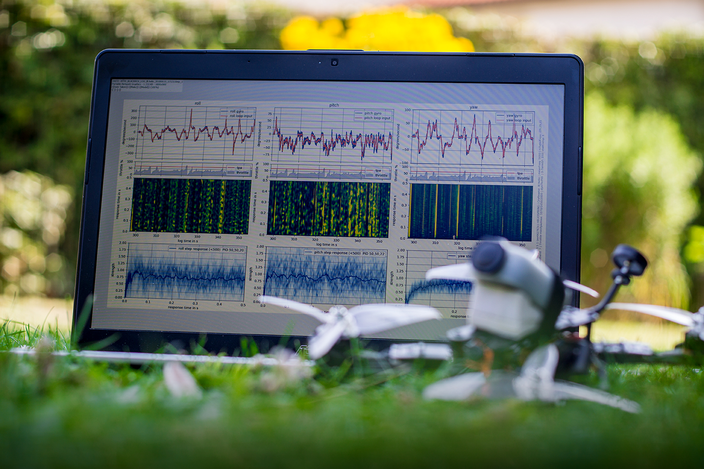
[/vc_column_text][vc_single_image image=”2920″ img_size=”large” onclick=”link_image”][vc_column_text]The response plot window is divided into three columns, one for each axis roll, pitch and yaw correspondingly. The top of the response plot window is reserved for the gyro / PID loop graphs. Ideally, the graphs should match each other. The overshoots and vibrations are visible as a difference between the two graphs.
The TPA influence on each axis is represented in the row below. The red line represents the TPA value. The PID gains are reduced when the throttle reaches and goes above the red line.
The next row is a graphical representation of the response time in correspondence to the throttle value. The blue areas are good and the yellow ones have more latency thus having a sluggish response.
The last row at the bottom is by far the most important one for the tuning process, it is the step response for each axis. The blue line represents the step response for inputs below 500 deg/s (center stick response), and the orange one is for inputs above that value (full stick response).
The wider area above and below the plot curves represents the noise level. This is a good sign of how your filtering is doing its job. The better the filtering is adjusted on your fpv drone, the narrower this area gets.
Noise Plot
[/vc_column_text][vc_single_image image=”2921″ img_size=”large” onclick=”link_image”][vc_column_text]For you to properly use the noise plot, you should enable the debug mode on your flight controller by setting it to Notch or Gyro_scaled for the newer Betaflight versions.
If you are using Plasmatree for filter tuning your blackbox logging rate should be 2-4k for 8k looptime and gyro sampling rate and 4k or 8k+ for 16k or 32k looptime and gyro sampling rate.
You can use the noise plot for determining the noise levels over frequency depending on the throttle amount and the way your current filter settings are affecting the noise filtering.
The Layout
The main area of the noise plot screen is dedicated to the noise graphs. The post filtered and pre-filtered gyro noise graphs on all axes are on the left side. The D-term noise graphs or the amount of noise getting to the PID controller for pitch and roll and the filter effectiveness graphs are on the right side of the noise plot screen.
If you have already used the Blackbox Explorer for determining the noise levels and filtering frequencies, you should already be familiar with the noise plot. The difference is that the amount of noise on these graphs is color-coded in the third axis, similar to a topo map, where the blue color represents low noise, and the yellow color represents higher noise levels.
The noise graphs have auto-scaling enabled so sometimes it may seem that the filtered graphs have more noise than the unfiltered. You can see the noise intensity scale and range on top of each graph over the color gradient band.
If you are beginner pilot, you should look for the yellow areas in the debug graphs on the left to determine the frequency with higher noise levels, and you should use that info to set your gyro notch filters range. The similar thing goes for the D-term noise level and filtering.
Here is a useful video from Joshua Bardwell on configuring the Betaflight notch filters:[/vc_column_text][vc_video link=”https://www.youtube.com/watch?v=iUASxYf-6sg”][vc_column_text]The graphs on the far right are another representation of the filtering effectiveness. The lower the transmission percentage, the better job your filters are doing their job.
Practical Use
To receive proper data and achieve the best results from the Plasma Tree PID Analyzer, first, your fpv drone should be set up correctly.
First, check and tighten all bolts on the motors and the frame. Check that there is no damage on the propellers and that all blades are in line or use new propellers for best results.
It is advisable to have your flight controller and motors soft mounted.
You should have proper filtering to prevent the excessive noise coming to the gyro and the PID controller. This is individual for each fpv drone. If you are unfamiliar with filter setup, there is plenty of info available on YouTube or in a worst-case scenario, you can use the default filtering values that come with your firmware.
Other than the filtering, you should set your D-setpoint weight to 0, TPA to 0, VBAT Compensation to ON, Antigravity to OFF and set debug_mode=notch in the CLI. Also, if you are using Betaflight 3.4, disable the Smart_Feedforward feature while doing the PID Analyzer tuning.
By changing the D-setpoint weight, TPA and Antigravity, you are preventing any dynamic modification of the PID parameters, and you are only compensating for the battery voltage drop.
Lastly, for PID tuning you should set your blackbox logging rate to 1-2k+.
The Tuning Process
For best results, you should start tuning by zeroing or lowering the I and D to 5 or 10 and setting the P on pitch and roll to 20 first.
It is advisable to record multiple logs with different PID settings so you could compare the plots and get an insight into how the PID parameters change affects the plot data. You will get separate plots for each log. This will speed up your tuning process.
With the above settings applied, you are ready to go out and fly. Only 20 seconds of data are required. Also, there is no need of fpv flying, you can do a line of sight flight and just shake the fpv drone back and forth on all axes. Please note that if it is windy, you should up the flight time to about 40-50 seconds so you could have enough log data for the PID Analyzer to process.
Go out and fly for about 20 to 40 seconds, land, increase the P by 10, and repeat the cycle until you reach a value of 60. Land and process the logs through the PID Analyzer, specifying plot name for example “tune_P.”
The PID Analyzer will output five plots with a visible difference from the gradually increased P gain.
In my case, the output graphs looked something like this:[/vc_column_text][vc_single_image image=”2922″ img_size=”large” alignment=”center” onclick=”link_image”][vc_column_text]
P gain influence
The P gain influences the step response strength. Low P values produce plot curve that is reaching strength value of 1 relatively slow or not reaching it at all, and too high P gain produces an oscillating curve thus reaching a strength of 1 several times. The proper P gain value should produce a curve plot that reaches a strength of 1 or higher only once as fast as it could in the range of 0.0 to 0.1 response time and then continues settling on an approximate value that is lower or near 1.
After you have chosen the most appropriate P gain, it is time to repeat the whole tuning cycle again, but this time by increasing, then I gain values by 10 each time.
Here is my set of processed logs displaying the increase of the I gain from 10 to 50:[/vc_column_text][vc_single_image image=”2924″ img_size=”large” alignment=”center” onclick=”link_image”][vc_column_text]
I gain influence
Increasing the I gain will rise and smooth out the graph curve to a strength value of 1. If your I values are too high, the produced graph curve will have a certain amount of waviness to it. If the I values are too low, the graph curve will only reach the strength equal to 1 in the range of 0.0 to 0.1 response time and will tend to have lower strength value after that.
Once again, repeat the whole cycle for the D gain by increasing it by 5 each time.
The increase of the D gain produced the following 5 plots in my case:[/vc_column_text][vc_single_image image=”2925″ img_size=”large” onclick=”link_image”][vc_column_text]
D gain influence
The increase of D gain tends to reduce the overshoot that the Plasmatree plot curve has in the range of 0.0 to 0.1 response time, and it tends to lower it to a strength value close to 1. Too low value produces plots that have a noticeable initial rise over 1 reaching strength values of 1.25 or even 1.5 and too high values produce plot graphs that have a small hump in the range of 0.0 to 0.1 response time, with a maximum strength value lower than 1 and slowly rising to strength value of 1 after that.
The yaw plot curve will tend to look a bit different from the above samples because the yaw axis has not that much authority than the pitch and roll axes.
Briefly, if your Plasmatree graphs show overshoot, you should turn down P term or rise D term. If the graph looks bumpy, you should raise I term, and if the graph looks over dampened, you should lower D term or raise P term always bearing in mind that too high D term values may smoke up your motors.
Here is the final result from my Plasmatree PID Analyzer tuning:[/vc_column_text][vc_single_image image=”2926″ img_size=”large” onclick=”link_image”][vc_column_text]
Lowering the response time
One last thing in regards to the tuning is lowering the response time. This could be accomplished by increasing the P and D values proportionally. The step response should get to a value of 1 in lowest possible time, which could be achieved by increasing the P value, but in the same time, the D should be increased proportionally to avoid overshoot and keep the strength near the value of one.
You could calculate the proportional raise of P and D by using the following formulas provided by YouTube user Wüdz_fpv
(D1/P1)*P2 = D2 and (P1/D1)*D2 = P2
Once again, doing this could lead to hot motors or even motor failure so you should gradually raise the P and D values and check your motor temperature continuously while doing that.
Conclusion
For the experienced pilots, Plasmatree provides excellent insight into the way your current PIDs are affecting the flight characteristics of your fpv drone and helping you realize the ways that you could improve and refine your PIDs.
If you are beginner pilot, Plasmatree may help you tune your fpv drone much faster than with the regular trial and error tuning process. You should also note that the default Betaflight PIDs fly great, so it is better to spend your time flying and building rather than trying to improve your tune with Plasmatree.
Massive thanks to the GitHub user Plasmatree, the author of the PID Analyzer for the time and effort he has put into the development of this tool.
If you need more help with tuning, be sure to visit the official RC Groups thread.
Great article, I have been looking for this type of content for a few weeks now. Other videos and articles seem to be guessing how the PIDs changed the graph. I love the real world example you did.
One question, that I have not seen answered yet, what changes are needed for Betaflight 3.5?
Thanks, Robert.
In regards to the changes in Betaflight 3.5 I haven’t tried it yet but as I understand the Feedforward has no effect on the actual pids in the way the setpoint weight had, so there is no need to change the default value when tuning. Everything else should be the same as on Betaflight 3.4.
To be on the safe side, you can try and do some tests with normal Feedforward values and zeroed Feedforward values, so you could compare the graphs and see if there is any change in the PID gain values.
What a great tool. I’m not able to locate the windows download link. Thanks.
Thanks for pointing out, I have updated the links.
You can download the Windows version of the PIasmatree PID Analyzer here:
https://github.com/Plasmatree/PID-Analyzer/releases
sounds great
Nice tool. Bet you get a lot.😊😊😂😊