

There is a new class of quadcopters making a rise in the FPV market, called the toothpick class. These quads are extremely lightweight, 2.5-inch builds that have high efficiency, and an insane thrust to weight ratio. The toothpick has been popularized by KababFPV, a freestyle pilot and quad reviewer.[vc_row][vc_column width=”1/6″][/vc_column][vc_column width=”2/3″][vc_single_image image=”5186″ img_size=”full” alignment=”center” onclick=”link_image”][vc_column_text]
This article was submitted through the GetFPV Community Program by Lawrence Ro.
Disclaimer: This article was written solely by a member of the FPV Community. Views and advice in this article are that of the author and does not necessarily reflect the opinion or views of GetFPV.
[/vc_column_text][/vc_column][vc_column width=”1/6″][/vc_column][/vc_row][vc_row][vc_column][vc_column_text]
Rise of the Toothpick
Now, how did the toothpick class come to be? Well, although this type of quad has been around for quite some time now, KababFPV pushed the development of it by initially slapping the Mobula7 electronics onto a home-built frame and mounting a tiny all-in-one camera. He also initially used the 65mm KINGKONG props for their high efficiency and thrust.
When he put everything together, it flew for longer and faster than his original Mobula7. The reason for this? He says that the secret is in the motor/prop/XT30/weight combo. By using 1103 motors, with 65mm (2.5-inch) prop, an XT-30, and keeping the AUW (all up weight) under 70g, the aircraft flies just like a 5-inch quadcopter, but with less “throw” during acro.
The XT-30 connector is a vital component here, as it allows for a larger amount of current to go from the battery to the quad. This means more thrust, less voltage sag, and longer flight times.
On another note, the flight times for these quads are insane! On a basic 1103/65mm prop/450mah 2s setup, expect to get anywhere from 5-8 minutes of spirited acro FPV! Also, these builds are cheap. Expect to pay anywhere from $100-$150 for a top of the line build that flies amazingly.
Now, after much research and development, he has released a frame designed for the following parts:
- 1103 8000-11000KV motors
- 65mm props
- Any AIO brushless whoop board
- 450mah 2S lipo
- AIO FPV camera or nano FPV camera
[/vc_column_text][/vc_column][/vc_row][vc_row][vc_column][vc_column_text]
Components
Here is my version of the build, which heavily utilizes parts from BetaFPV. The reason for this is because the BetaFPV parts have high quality components and require minimal soldering. You can grab all these parts below at GetFPV’s shop and be flying today![/vc_column_text][/vc_column][/vc_row][vc_row][vc_column width=”1/3″][vc_single_image image=”5190″ alignment=”center”][dt_default_button link=”url:https%3A%2F%2Fwww.getfpv.com%2Fkababfpv-toothpick-frame-kit-110x-motor-mount.html||target:%20_blank|” button_alignment=”btn_center”]KababFPV Toothpick Micro Frame Kit[/dt_default_button][ultimate_spacer height=”10″][vc_single_image image=”5195″ alignment=”center”][dt_default_button link=”url:https%3A%2F%2Fwww.getfpv.com%2Fz02-aio-camera-5-8g-vtx-wired-version-with-25-35-mount.html||target:%20_blank|”]Z02 AIO Camera with 5.8Ghz VTX[/dt_default_button][/vc_column][vc_column width=”1/3″][vc_single_image image=”5192″ alignment=”center”][dt_default_button link=”url:https%3A%2F%2Fwww.getfpv.com%2Fbetafpv-f4-2-4s-12a-blheli-s-aio-brushless-flight-controller-second-version.html||target:%20_blank|” button_alignment=”btn_center”]BETAFPV F4 2-4S 12A AIO Flight Controller[/dt_default_button][ultimate_spacer height=”10″][vc_single_image image=”5196″ alignment=”center”][dt_default_button link=”url:https%3A%2F%2Fwww.getfpv.com%2Ffrsky-r-xsr-2-4ghz-16ch-accst-micro-receiver-w-s-bus-cppm.html%23gallery-1||target:%20_blank|”]FrSKy R-XSR 2.4GHz 16Ch ACCST Receiver[/dt_default_button][ultimate_spacer height=”10″][vc_single_image image=”5197″ alignment=”center”][dt_default_button link=”url:https%3A%2F%2Fwww.getfpv.com%2Ftattu-650mah-2s1p-75c-7-4v-lipo-battery-pack-with-xt30-plug.html||target:%20_blank|”]TATTU 650mAh 2S1P 75C 7.4V Lipo Battery Pack with XT30[/dt_default_button][/vc_column][vc_column width=”1/3″][vc_single_image image=”5193″ alignment=”center”][dt_default_button link=”url:https%3A%2F%2Fwww.getfpv.com%2Fbetafpv-1103-8000kv-brushless-motors.html||target:%20_blank|”]BETAFPV 1103 8000Kv Brushless Motors[/dt_default_button][ultimate_spacer height=”10″][vc_single_image image=”5194″ alignment=”center”][dt_default_button link=”url:http%3A%2F%2FPyrodrone%2065mm%20Toothpick%20Propeller||target:%20_blank|” button_alignment=”btn_center”]Pyrodrone 65mm Toothpick Propellers[/dt_default_button][/vc_column][/vc_row][vc_row][vc_column][ultimate_spacer height=”40″][/vc_column][/vc_row][vc_row][vc_column][vc_column_text]
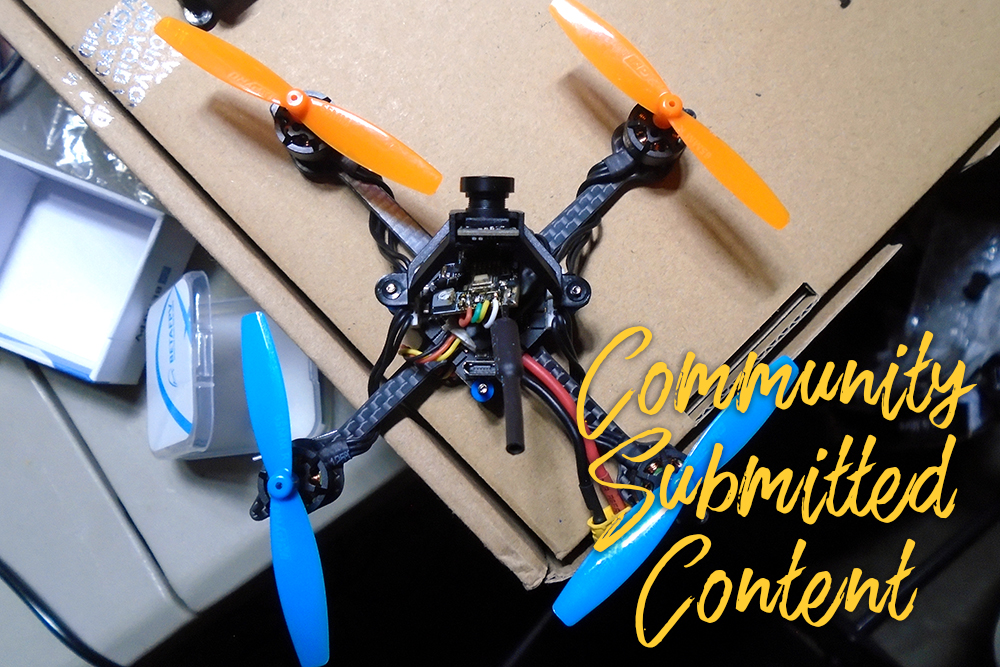
Building the Quad
Taking everything out of the bag that comes with the KababFPV toothpick frame, you are presented with the frame, an XT-30 connector, and a plethora of high-quality screws and nuts.
The general way to build this frame is to put the screws through the four mounting holes facing up, with the nuts securing the screws to the frame. The nuts double as a spacer for the flight controller, which is a good thing, since carbon fiber is conductive without its outer coating. I used the four longest screws to poke up through the board and secure with the nuts.
The frame already comes with sanded/rounded corners to increase durability, so there is no need to sand the frame in any way.[/vc_column_text][/vc_column][/vc_row][vc_row][vc_column][vc_column_text]
Mounting Motors
First off, the motor mounting. This is a straightforward process which requires little time to do. Remember to use the screw that came in the bag with the motors, because the screws that come with the toothpick frame are a little bit too wide for the BetaFPV motors.[/vc_column_text][/vc_column][/vc_row][vc_row][vc_column width=”1/2″][vc_single_image image=”5200″ img_size=”full” alignment=”center” onclick=”link_image”][/vc_column][vc_column width=”1/2″][vc_single_image image=”5201″ img_size=”full” alignment=”center” onclick=”link_image”][/vc_column][/vc_row][vc_row][vc_column][vc_column_text]The BetaFPV 1103 motors have a four-screw mounting pattern, in comparison to the three- hole mounting pattern common in other motors of this size. Due to this, the motor holes are a little bit too large for this frame, so only two screws opposite to each other are needed. Not only does this decrease weight but having two screw on such a small build should not matter as much as in a larger, lets’ say, a five-inch build.[/vc_column_text][/vc_column][/vc_row][vc_row][vc_column width=”1/6″][/vc_column][vc_column width=”2/3″][vc_single_image image=”5202″ img_size=”full” alignment=”center” onclick=”link_image”][/vc_column][vc_column width=”1/6″][/vc_column][/vc_row][vc_row][vc_column][vc_column_text]
Soldering
Next up comes the soldering for the flight controller. This is probably the hardest part of this whole build, so you’ll need a high-quality iron with a precise tip. I would recommend something like a TS100 to get the job done.
Solder three wires to the pins 5V, Gnd, and Sbus. These wires will be connected to your Sbus receiver. Since I am using the Frsky R-XSR with the F-port protocol, I only need three wires to get power and communications to it.[/vc_column_text][/vc_column][/vc_row][vc_row][vc_column width=”1/6″][/vc_column][vc_column width=”2/3″][vc_single_image image=”5204″ img_size=”full” alignment=”center” onclick=”link_image”][/vc_column][vc_column width=”1/6″][/vc_column][/vc_row][vc_row][vc_column][vc_column_text]Now for the OSD wiring. There are four main pads the be soldered: Voltage, Ground, Video IN, and Video OUT. The V+ and Gnd send power to your video transmitter. This power is then filtered and regulated for powering your FPV camera.
The Video IN pin connects to the FPV camera. This is then sent through the OSD chip in the flight controller, and then goes through the Video OUT pin. The video transmitter’s input wire plugs into this pin. This means that the camera output and the Betaflight OSD can be displayed in the video transmitter’s output.[/vc_column_text][/vc_column][/vc_row][vc_row][vc_column width=”1/6″][/vc_column][vc_column width=”2/3″][vc_single_image image=”5205″ img_size=”full” alignment=”center” onclick=”link_image”][/vc_column][vc_column width=”1/6″][/vc_column][/vc_row][vc_row][vc_column][vc_column_text]Solder one last wire to the Smart Audio pin of the board. It should be under a “Tx” UART, because the flight controller is sending a signal through the wire to the video transmitter, allowing us to change video channels, power output, channel band, and frequency.[/vc_column_text][/vc_column][/vc_row][vc_row][vc_column][vc_column_text]
Mounting the Flight Controller
Using the blue rubber grommets, carefully mount the flight controller onto the frame. I found that by placing the grommets on the board, and then lowering it down on the mounting screws worked the most effectively. I had to mount the board upside down to allow for easy access to the USB port on it. Also, the motor connectors were faced up this way, which made everything much easier.[/vc_column_text][/vc_column][/vc_row][vc_row][vc_column width=”1/6″][/vc_column][vc_column width=”2/3″][vc_single_image image=”5206″ img_size=”full” alignment=”center” onclick=”link_image”][/vc_column][vc_column width=”1/6″][/vc_column][/vc_row][vc_row][vc_column][vc_column_text]The rubber grommets do a nice job in dampening vibrations going to the gyro in the flight controller. This should have a positive effect on the flight, as there will be less vibrations and the aircraft will feel a bit more locked-in while flying. Now that the board is nice and secure, it’s time to connect your motors.[/vc_column_text][/vc_column][/vc_row][vc_row][vc_column][vc_column_text]
Connecting Motors
Since the BetaFPV system uses motor connectors, the wiring of the motors is relatively easy. Simply wrap your motor wires one time around the frame arms, and then plug them into the board. Be careful, because this is a pretty tight fit! The orientation of the board and motor wires do not matter, since you can configure the rest in BL_Heli and Betaflight.[/vc_column_text][/vc_column][/vc_row][vc_row][vc_column width=”1/2″][vc_single_image image=”5210″ img_size=”full” alignment=”center” onclick=”link_image”][/vc_column][vc_column width=”1/2″][vc_single_image image=”5208″ img_size=”full” alignment=”center” onclick=”link_image”][/vc_column][/vc_row][vc_row][vc_column][vc_column_text]Another way to connect the motors up is to keep the three wires flush with the frame arms. Then, use a small piece of electrical tape or heat shrink to secure the wires to the frame. Plug in the motor wires to the 1.25mm connectors, and you’re good to go!
Connecting the motor wires with the electrical tape protection is technically a better way than simply wrapping the wires around the arm, mainly because the tape will protect the wires from a bent prop spinning in the event of a crash. Also, it looks a bit cleaner and nicer aesthetically.[/vc_column_text][/vc_column][/vc_row][vc_row][vc_column][vc_column_text]
FPV Setup
The FPV setup is all up to you in this build. I personally use the BetaFPV Z02 AIO FPV camera. It can output 25-200mW, has OSD capability, Smart Audio, and comes with a camera mount. Also, the image quality looks fantastic on it, with great WDR and a sharp image.
Here is how the general connection for these FPV setups go:
- FC V+ –> VTX V+
- FC Ground –> VTX Ground
- FC Video In –> FPV Camera Video Out
- FC Video Out –> VTX Video In
- VTX 5V –> FPV Camera Video 5V
- VTX Ground –> FPV Camera Video Ground
[/vc_column_text][/vc_column][/vc_row][vc_row][vc_column width=”1/2″][vc_single_image image=”5212″ img_size=”full” alignment=”center” onclick=”link_image”][/vc_column][vc_column width=”1/2″][vc_single_image image=”5209″ img_size=”full” alignment=”center” onclick=”link_image”][/vc_column][/vc_row][vc_row][vc_column][vc_column_text]
Cleanup
Now for the easy part; the build cleanup! This involves the final mounting of the camera, shortening any stray wires, and in general making the build cleaner. I would recommend snipping your receiver wires so that there is not excess wire hanging off the side. Also, make sure that the OSD wires aren’t too long.
To make your wiring tidier, try twisting each bunch of wires going to each component. For example, twist the three wires going to your receiver (5V, Gnd, Sbus), and then twist the five wires going to the OSD (5V, Gnd, IN, OUT, Smart Audio).
By doing this, you will minimize the chance of stray wires getting caught in the props during flight, and the twisting of the wires reduces electrical interference caused by magnetic currents generated by the wires while powered on.
Another tip pertaining to the receiver antennas is to mount them 90 degrees from each other. This will maximize range, and by mounting them on the frame arms, the antenna orientation works out perfectly. If you heat shrunk or taped your motor wires down, then you could just slip the receiver antennas right alongside the tape on the arm for a slick way to mount your antennas.
To mount your FPV camera, simply use the underside screws securing the flight controller to screw the FPV mount in. If you are using the BetaFPV Z02 AIO FPV camera, then the included mounts work perfectly, and reduce vibrations due to their flexible nature.[/vc_column_text][/vc_column][/vc_row][vc_row][vc_column][vc_column_text]
Betaflight
Betaflight configuration should be relatively straightforward. Basically, setup everything as you would in a mini quad. However, there were some setbacks that I experienced. The Betaflight target for the BetaFPV board is the “MATEKF411”.
If you mounted the flight controller in a different way, the board alignment may need to be changed. Also, the motor mapping needs to be changed if your motors are not spinning in the desired direction.[/vc_column_text][/vc_column][/vc_row][vc_row][vc_column][vc_single_image image=”5213″ img_size=”full” alignment=”center” onclick=”link_image”][/vc_column][/vc_row][vc_row][vc_column][vc_column_text]I am running my toothpick with the “props out” configuration. This means that the motors in the front and back spin away from each other instead of spinning towards the center of the aircraft. I found that the “props out” configuration gives me a little bit better handling in the corners and less propwash, as compared to the “props in” configuration.[/vc_column_text][/vc_column][/vc_row][vc_row][vc_column][vc_column_text]
Conclusion
Overall, the toothpick class is a growing class of quads. They are gaining a huge following in the FPV community, and I encourage you to try out a build. They have excellent flight characteristics, long flight times, and are cheap and easy to build.
On this particular build, I got over 11 minutes of flight time on a 650mah 2S LiPo! Normal quads have flight times of 2-5 minutes, so if you pick up a few LiPos for these quads, you can have hours of flight time in a mere handful of LiPos!
If building doesn’t seem to be your thing, you can always opt for purchasing a pre-built quad such as the Emax TinyHawk or iFlight TurboBee, which will get you up in the air faster.[/vc_column_text][/vc_column][/vc_row]